
Low pressure generating plasma reactor closed loop process and system

a plasma reactor, low-pressure technology, applied in chemical/physical/physical-chemical processes, nitric oxides, nitrate oxides, etc., can solve the problems of reducing the industrialization of low-pressure technologies, requiring significant absolute pressure of 0.2 bar, and reducing the efficiency of low-pressure production

Pending Publication Date: 2021-12-30
N2 APPLIED
View PDF0 Cites 0 Cited by
  • Summary
  • Abstract
  • Description
  • Claims
  • Application Information

AI Technical Summary

Benefits of technology

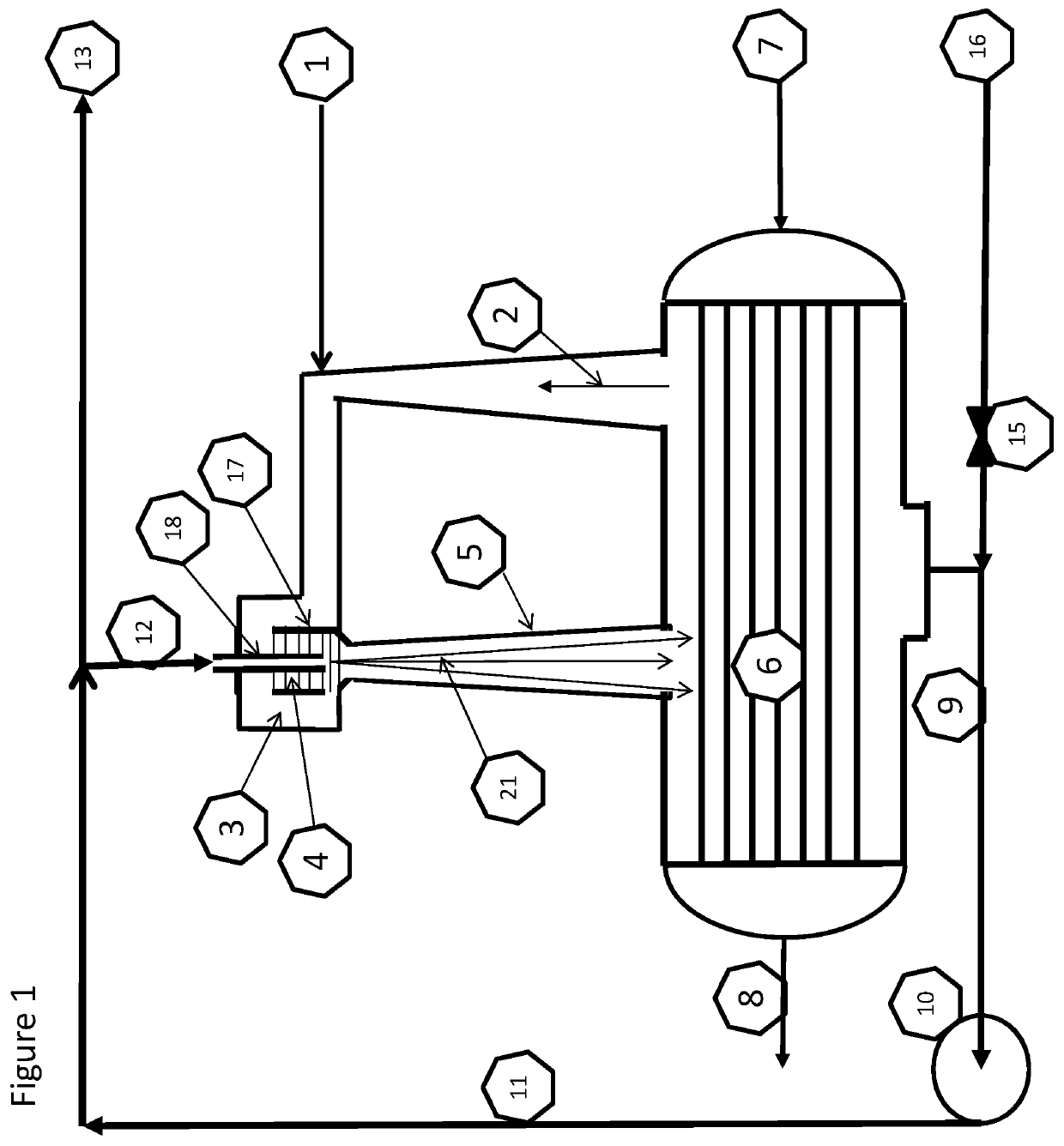
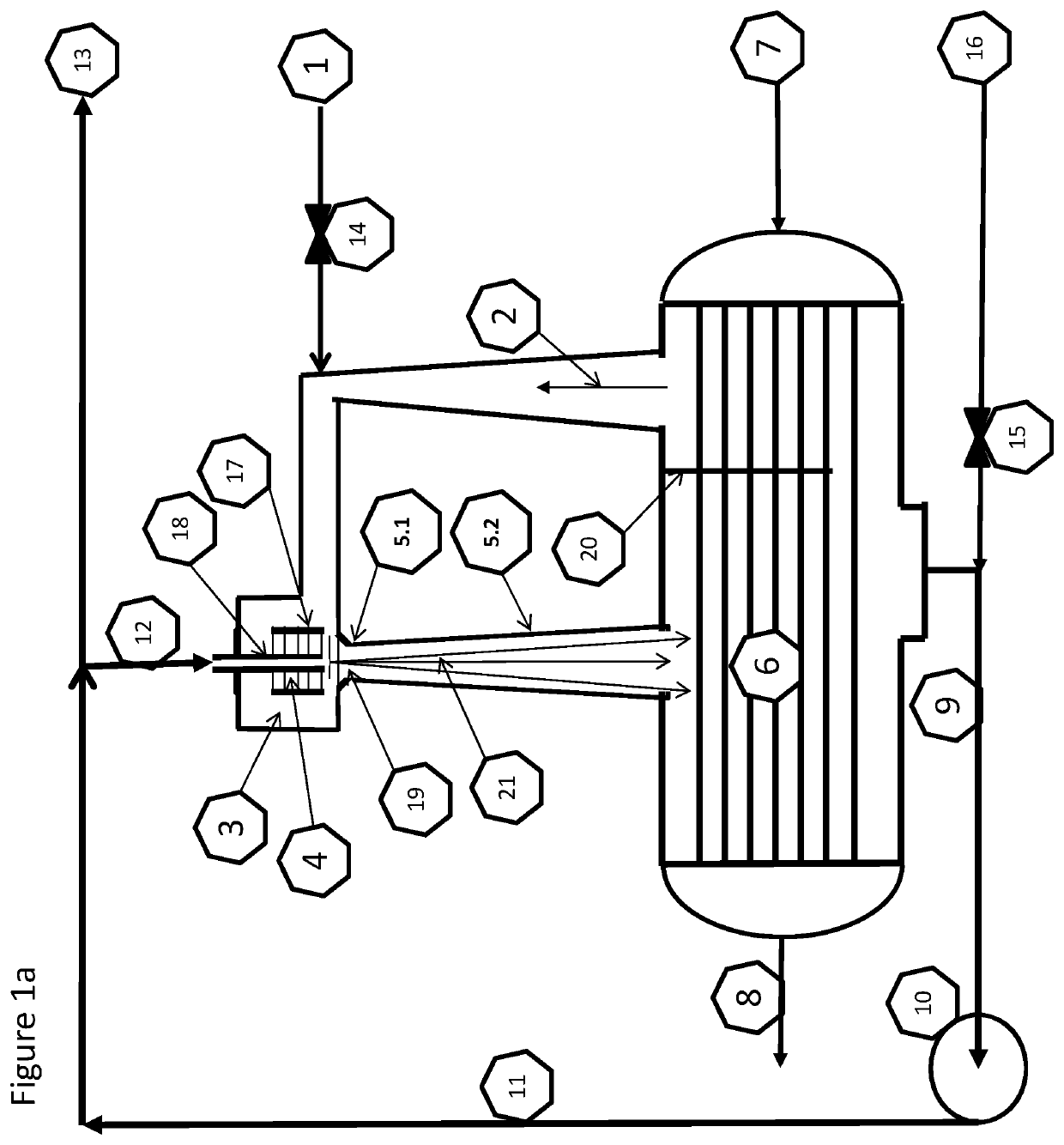
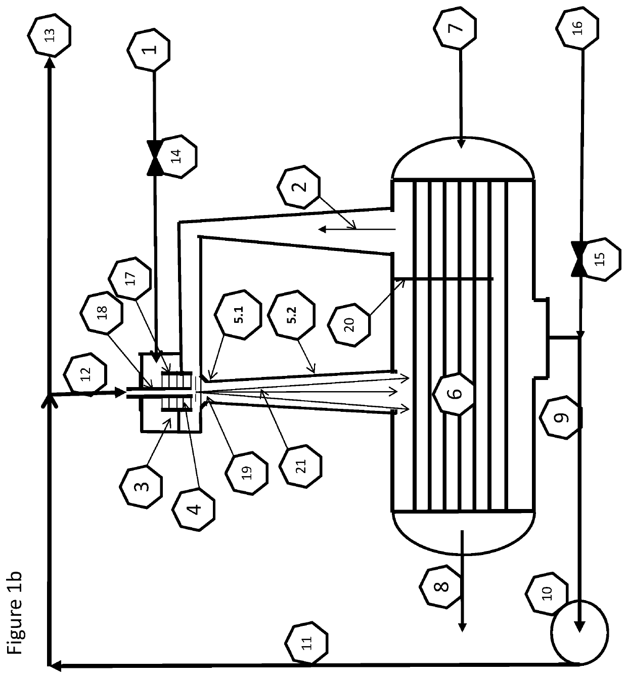
The patent is about a process where a device called an ejector is used to reduce the pressure in a plasma generator and the products it creates. This is done by using a circulating absorption liquid as a motive fluid in the ejector. The process also includes adjusting the ratio of the feed gas to the absorbed plasma products to avoid buildup of unreacted gas. The technical effect of this invention is that it helps to create a more efficient and effective plasma generation system.

Problems solved by technology

The energy required to create an absolute pressure of 0.2 bar is significant, and this energy requirement has inhibited the industrialization of technologies using low pressure.
The cost of doing an air separation to overcome the stoichiometric imbalance is also costly and making an otherwise elegant process more complicated.
The disadvantage of combining a low yield plasma process for making 2% NO at atmospheric pressure is the energy cost of heating the air to facilitate the breakdown of the air at between 3500-6000 Kelvin, the energy cost is theoretically more than 400 GJ / tN.
The disadvantage of operating a low yield plasma process at a pressure of less than 0.2 bar, is the cost of creating the vacuum, being minimum 20 GJ / tN.
The disadvantage of operating a low yield once through process making 2% NO is the cost of cleaning and treating the unreacted gas flow.

Method used


Image

  • Low pressure generating plasma reactor closed loop process and system
  • Low pressure generating plasma reactor closed loop process and system
  • Low pressure generating plasma reactor closed loop process and system

Examples


example 1

om Air and Water

[0137]The fresh feed air 1 to the plasma synthesis loop can be fed in 1.1 to the plasma zone 4.1 and the recycle gas 2 containing nitrogen and steam from the condenser 6 can be used as quenching air 1.3. The fresh feed can alternatively be directed to 1.2 as quenching gas 1.3 with steam and surplus of nitrogen in 2 from the condenser 6. Both alternatives are although locked to the following stoichiometries:

8N2+2O2+7H2O=7NO+3NO2+6NH3  XII

[0138]The stoichiometric absorption step may also take additional oxygen from water to form the intermediate acidic products:

8N2+2O2+22H2O=8HNO3+HNO2+7NH4OH  XIII

[0139]The full mass balance from air, steam and water is giving an alkaline solution if there is no extra oxygen provided:

8N2+2O2+26H2O=7HNO3+9NH4OH  XIV

[0140]The results and simulations show that the reaction path according to equation XII is the dominant one for the conditions acquired in the loop and described herein. The ratio between NOx and NHx is clearly on the acidic ...

example 2

Plasma Quenched with Water or Steam

[0141]Equation XVII indicates the potential for a significant surplus of Nitrogen, due to the initial N to O ratio in air. This means that it can be possible to feed in 1.1 the plasma zone 4.1 with pure nitrogen and quench it with water.

4N2+10H2O=2NO+2NO2+8NH3  XVII

The products from XVII is directly absorbed in water according to:

2NO+2NO2+8NH3+10H2O=4HNO2(aq)+8NH4OH(aq)  XVIII

[0142]The nitrous acid HNO2 is further oxidized in the oxidation tower 22 where the reaction to nitric acid is completed. The oxidizer receives a surplus of air and there is a stoichiometric surplus of nitrogen which will be released to the atmosphere:

4HNO2(aq)+8NH4OH(aq)+2O2+8N2=4HNO3(aq)+8NH4OH(aq)+8N2  XIX

example 3

a Quenched with Carbon Dioxide

[0143]Air plasma quenched with CO2 give from the overall stoichiometry the two main products, HNO3 and carbon as C2 and C3. From FIG. 1c, the carbon dioxide feed in 1.2 will provide enough oxygen for the air fed in 1.1 for a full oxidation to nitric acid inside the plasma synthesis, obsoleting the oxidation loop giving an overall mass balance:

8N2+2O2+8H2O+5CO2=C2+C3+16HNO3(aq)  XX

Alternatively, the carbon dioxide is fed in 1.1 and the air is fed in 1.2.

[0144]Inside the oxidation loop however, the active carbon components will eliminate the free oxygen and the reaction path will be dominated by the recycled nitrogen and carbon dioxide:

N2+CO2+H2O=½C2+2HNO3(aq)  XXI

[0145]The carbon molecules will precipitate in the water and follow the product out as active carbon.


PUM

PropertyMeasurementUnit
pressureaaaaaaaaaa
pressureaaaaaaaaaa
pressureaaaaaaaaaa

Abstract

The present invention provides a low pressure generating plasma reactor closed loop process, comprising: feeding a fresh feed gas flow and a fresh feed absorption liquid flow to a plasma reactor closed loop comprising a condenser, a liquid loop, a recycle gas loop, and a plasma generator; converting feed gas to reactive plasma products in the plasma generator; quenching and absorbing the reactive plasma products into an absorption liquid circulating in the liquid loop where the reactive plasma products react to form liquid reaction products, thereby generating low pressure in the closed loop; monitoring the composition and low pressure of the recycle gas loop and, if the pressure increases, adjusting the composition of the fresh feed gas flow and / or fresh feed absorption liquid flow to bring the composition of the feed gas towards stoichiometric ratio with the absorbed reactive plasma products; extracting circulating absorption liquid, containing the liquid reaction products, from the plasma reactor closed loop as a product flow. The present invention also provides a low pressure generating plasma reactor closed loop system, comprising a plasma generator, a condenser, a recycle gas loop, a liquid loop, and a pump.

Description

TECHNICAL FIELD OF THE INVENTION[0001]The present invention relates to a low-pressure generating plasma reactor closed loop process and system. The closed synthesis loop is especially suited to produce low-pressure plasma from air and absorbing the NO containing plasma in water or a watery solution. The synthesis system can handle solid feed in the form of suspended material or fluidized powder.BACKGROUND OF THE INVENTION[0002]Plasma generation is in general to excite gas molecules with high-energy electrons from an electric arc, electro-static or electro-dynamic field, Nano pulsed electric field, dielectric barrier discharge, laser-, radio- or micro-waves. Plasma can also be formed thermally or from chemical reactions or heat transfer.[0003]The electrical field is accelerating the electrons and the achieved energy is depending on mean free path for the electron. The mean free path depends on the concentration of gas molecules. The key parameter is the combination of the field stren...

Claims


Application Information

Patent Timeline
Patent Type & Authority Applications(United States)
IPC IPC(8): B01J19/08B01J19/24B01J19/00C01B21/32C01B21/20
CPCB01J19/088B01J19/2465B01J19/0033B01J19/2475C01B21/32B01J2219/0884B01J2219/00162B01J2219/00182B01J2219/0894B01J2219/00051C01B21/203C01B21/30B01J10/00C01B21/24B01J2219/0879B01J2219/0877C05F3/00C05F5/00
Inventor INGELS, RUNE
Owner N2 APPLIED
Learn More