Method for delivering a molten silicon composition into porous substrates

a technology of porous substrates and molten silicon, applied in the direction of ceramicware, solid-state diffusion coating, application, etc., can solve the problems of high cost, high cost, and high cost of molten silicon carbide, and achieve good wettability of silicon carbid

Inactive Publication Date: 2000-08-29
SN DETUDE & DE CONSTR DE MOTEURS DAVIATION S N E C M A
View PDF10 Cites 47 Cited by
  • Summary
  • Abstract
  • Description
  • Claims
  • Application Information

AI Technical Summary

Benefits of technology

FIG. 8 shows an effect of treatment in accordance with the invention.
DETAILED DESCRIPTION OF PREFERRED EMBODIMENTS OF THE INVENTION
For simplification purposes, the description below relates to incorporating in porous substrates a composition based on elemental metallic silicon, i.e. an "Si-based" composition, which is a composition made exclusively or mostly of silicon, with the elements optionally added to the silicon being selected, for example, amongst: boron, aluminum, zirconium, hafnium, titanium, molybdenum, tungsten, tantalum, . . .
It will immediately be clear to the person skilled in the art that the methods described can be implemented with other metal-based compositions, in particular with compositions made exclusively or mostly of one or more metals which, like silicon, have a melting temperature that is compatible with the materials of the substrates to be treated, i.e. preferably a melting temperature that is lower than 2000.degree. C., and which are suitable for reacting with carbon to form refractory carbides, i.e. carbides having a melting temperature higher than 2200.degree. C. Apart from silicon, such metals comprise in particular titanium, zirconium, hafnium, a

Problems solved by technology

In addition, certain parts, in particular C--C composite parts, run the risk of floating on the surface of the bath because of their density being different from that of the bath.
The use of that technique raises difficulties associated with the complexity of assembly and with bulk, and also with removing the drain, since after cooling it remains welded to the resulting part.
The drawbacks that result from using that technique are significant loss of metal by runoff at the time of melting, the major risk of the part sticking to its support, and the need for subsequent machining of the outside of the part.
In addition, with parts of relatively large dimensions, processing them throughout their entire volume can require several successive operation

Method used


Image

  • Method for delivering a molten silicon composition into porous substrates
  • Method for delivering a molten silicon composition into porous substrates
  • Method for delivering a molten silicon composition into porous substrates

Examples


example 1

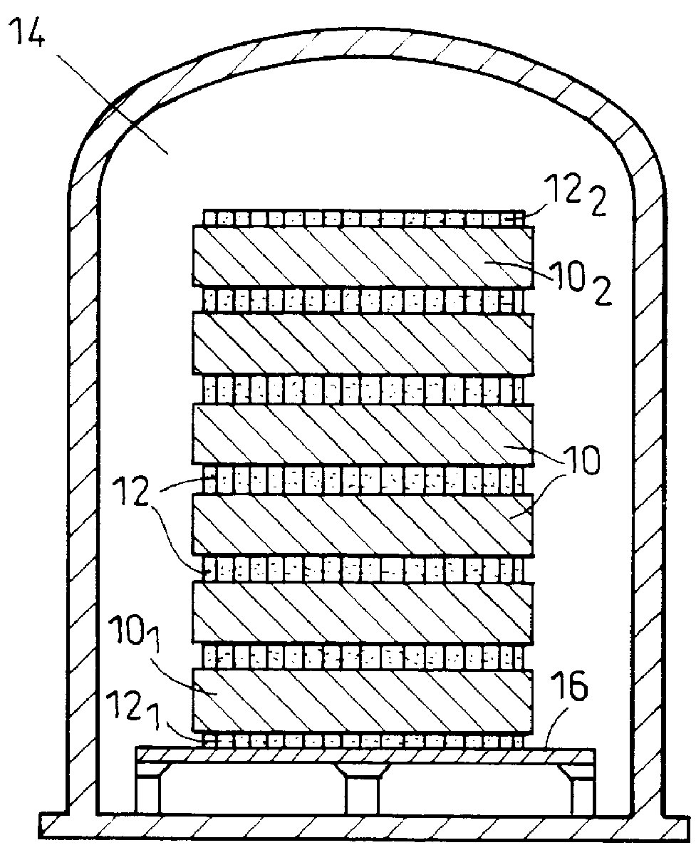
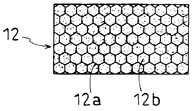
Two samples of C--C composite material in the form of rectangular parallelepipeds of thickness equal to 25 mm and having residual open pore space representing about 13% by volume, were placed one above the other. A source of silicon was placed between those two samples, which source was constituted by a honeycomb structure of C-phenol composite material having its cells filled with silicon powder. The honeycomb structure had a thickness of 10 mm and it represented 3% by volume of the source of silicon.

The assembly built up in that way was placed in a furnace and raised to a temperature of 1500.degree. C. at a pressure of 10 mbar of argon for 1 hour. After cooling, it was observed that the molten silicon had migrated both into the lower sample by gravity and into the upper sample by capillarity. 93% of the mass of silicon initially contained in the silicon source had migrated into the samples, and of the quantity that migrated, 46% was to be found in the upper sample and 54% in the l...

example 2

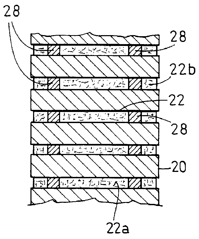
The procedure was the same as in Example 1 except that three samples of C--C composite material in the form of rectangular parallelepipeds were stacked with two interposed sources of silicon. The samples were blocks having a thickness of 22 mm with residual open pore space constituting 13% by volume, and the silicon sources were constituted by honeycomb structures having a thickness of 10 mm and filled with silicon powder.

After cooling, the stack was extracted from the furnace and it was observed that the samples were easily separated from the honeycomb structures which were then empty of silicon. The final amount of residual pore space in the bottom, middle and top samples were respectively equal to 8%, 3%, and 9% by volume. In conformity with the observation made in Example 1, it was the middle sample which received most silicon, given that it was in contact with a source of silicon via each face.

example 3

The procedure of Example 2 was followed, except that the sources of silicon used were constituted by honeycomb structures having a thickness of 15 mm and filled with silicon powder.

The final amount of residual pore space as measured were equal to 7%, 3%, and 6% for the bottom, middle, and top samples respectively. This example, in comparison with Example 2, shows that it is possible to vary the quantity of silicon incorporated in the samples by varying the thickness of the honeycomb structure, i.e. by varying the capacity of the sources of silicon.


PUM

PropertyMeasurementUnit
Fractionaaaaaaaaaa
Percent by massaaaaaaaaaa
Percent by volumeaaaaaaaaaa

Abstract

PCT No. PCT/FR96/01598 Sec. 371 Date May 13, 1998 Sec. 102(e) Date May 13, 1998 PCT Filed Oct. 14, 1996 PCT Pub. No. WO97/18176 PCT Pub. Date May 22, 1997A plurality of substrates (10) are disposed in alternation and in contact with layers (12) which constitute sources of metal-based composition, each layer comprising a majority phase formed by the metal-based composition and a minority phase suitable for forming a structure for retaining and draining the metal-based composition when it is in the molten state. The batch is heated to a temperature greater than the melting temperature of the metal-based composition such that the metal-based composition in the molten state can migrate from each source through the adjacent surface of the, or each, substrate adjacent to the source towards the inside of the substrate. The invention seeks in particular to incorporate a silicon-based composition in a thermostructural composite material, in particular a carbon-carbon composite material for siliciding purposes.

Description

The present invention relates to a method of incorporating a molten metal-based composition in porous substrates.In the present case, the term "metal-based" is used to mean more particularly a composition comprising one or more metals, preferably having a melting temperature that is lower than 2000.degree. C., and capable of forming refractory carbides having a melting temperature greater than 2200.degree. C. Such metals are, in particular, silicon, titanium, zirconium, hafnium, and vanadium.APPLICATION OF THE INVENTIONA particular field of application is incorporating a metal-based composition, and in particular a composition based on metallic elemental silicon (hereinafter an "Si-based" composition) in substrates of composite material, in particular of thermostructural composite material.Thermostructural composite materials are characterized by mechanical properties which make them suitable for constituting structural parts, and by their ability to retain these properties at high ...

Claims


Application Information

Patent Timeline
IPC IPC(8): C04B41/45C04B41/50C04B41/81C04B35/573C04B35/565C04B41/87C23C10/44C23C10/00C23C26/02F16D69/02C04B35/56C04B35/563C04B41/88
CPCC04B35/573C04B41/009C04B41/4513C04B41/4523C04B41/5059C04B41/81C04B41/87C23C10/44C23C26/02F16D69/023F16D69/027C04B41/5096C04B41/5133C04B41/4556C04B35/52C04B35/83C04B38/00Y02T50/67C04B41/50Y02T50/60
Inventor REY, JACQUESLAXAGUE, MICHELBERNARD, BRUNO
Owner SN DETUDE & DE CONSTR DE MOTEURS DAVIATION S N E C M A
Why Eureka
Try Eureka