Process for producing photo-electricity generating device

a technology of photoelectricity and generating device, which is applied in the direction of electrolytic inorganic material coating, surface reaction electrolytic coating, coating, etc., can solve the problems of expensive vacuum apparatus, high preparation cost of target material, and inability to use vacuum process

Inactive Publication Date: 2000-09-26
CANON KK
View PDF2 Cites 260 Cited by
  • Summary
  • Abstract
  • Description
  • Claims
  • Application Information

AI Technical Summary

Problems solved by technology

However, the former zinc oxide layer having the light-confining effect as described above is generally formed by a vacuum production process, such as vacuum deposition by using resistance heating or electron beam, sputtering, ion plating or chemical vapor deposition (CVD), thus being accompanied with problems, such as an expensive preparation cost of a target material, the necessity of using a vacuum process, an expensive vacuum apparatus, and a low utilization efficiency of the materials used.
As a result, a photo-electricity generating device (e.g., solar cell) produced by the vacuum process becomes very expensive, thus constituting a barrier to industrial applications thereof.
Accordingly, if the resultant zinc oxide film having such an anomalous growth portion is used as a part of the photo-electricity generating device, the anomalous growth portion is liable to induce a shunt passing phenomenon in the photo-electricity generating device.
(3) When the zinc oxide film is applied to a photo-electricity generating device, adhesive properties between the zinc oxide film and an underlying layer (electroconductive substrate) and / or between the zinc oxide film and an overlying layer (semiconductor layer) become insufficient.
(4) The resultant zinc oxide film has a smooth (flat) surface, thus failing to provide a surface in an appropriate uneven shape providing the light-confining effect.
Al is inexpensive and thus suitable for the metal layer material but is dissolved in an aqueous solution comprising nitrate ions and zinc ions, so that it is difficult to effect electrodeposition of the zinc oxide layer on the Al layer.
Generally, a larger zinc nitrate concentration provides a larger crystalline size (particle size) of the zinc oxide layer, thus being liable to provide a surface unevenness.
Further, a lower solution temperature is liable to lead to a larger zinc oxide crystalline size.
The sharp pits 320 are not desirable since they are liable to cause a short circuit of the photo-electricity generating device.
As a result, in the subsequent etching step, ununiform etching is liable to occur, thus providing the gentle wavy surface as shown in FIG. 3B.
As a result, the photo-electricity generating device does not function as a practical photo-electricity generating device.
Below the above preferred ranges the anomalous growth cannot readily be suppressed.
The formation of the thicker zinc oxide layer is disadvantageous industrially and is expensive.
Further, when the lower layer is formed in a thickness below 0.5 .mu.m, a denseness of the resultant zinc oxide layer becomes insufficient, thus being liable to cause undesirable pits for the etching treatment.
When the upper layer is formed in a thickness of below 0.2 .mu.m, a density of generated pits necessary for the etching treatment becomes extremely small and a depth (height) of a surface unevenness after effecting the etching treatment becomes insufficient.
If the second zinc oxide layer is formed in a thickness of below 0.05 .mu.m, it is difficult to completely fill deep pits generated at the first zinc oxide layer surface.
Below 0.05 .mu.m, a resultant reflectance is undesirable decreased.
Above 0.5 .mu.m, the formation of such a layer becomes expensive.
As described hereinabove, however, it is difficult to directly deposit the zinc oxide layer on the Al layer by an electrochemical process (electroplating).

Method used


Image

  • Process for producing photo-electricity generating device
  • Process for producing photo-electricity generating device
  • Process for producing photo-electricity generating device

Examples


example 2

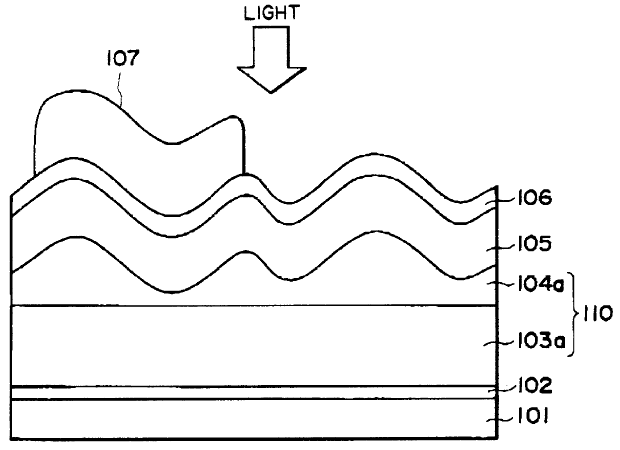
A photo-electricity generating device as shown in FIG. 1A was prepared and evaluated in the same manner as in Example 1 except that a zinc oxide layer consisting of an upper layer and a lower layer was formed under conditions shown in Table 2 and the etching conditions were changed to those shown in Table 2.

As a result, the photo-electricity generating device was found to show excellent photoelectric properties (photoelectric conversion efficiencies and short circuit currents) similar to those of the photo-electricity generating device of Example 1 (in comparison with Comparative Examples 1-A and 1-B).

Further, the photo-electricity generating device after effecting the HH and weathering tests was subjected to measurement of a leakage current in a dark place under application of a reverse bias voltage of 1.1 V.

As a result, the photo-electricity generating device provided the leakage current which was ca. 1 / 10 of that of the device of Comparative Example 1-A.

example 3

A 0.05 .mu.m-thick Al layer (backside reflection layer) and a 0.1 .mu.m-thick zinc oxide layer (intermediate layer) were successively formed on a continuous stainless steel (SUS430BA) sheet (width=30 cm, length=800 m, thickness=0.15 mm) by sputtering according to a so-called Roll-to-Roll scheme.

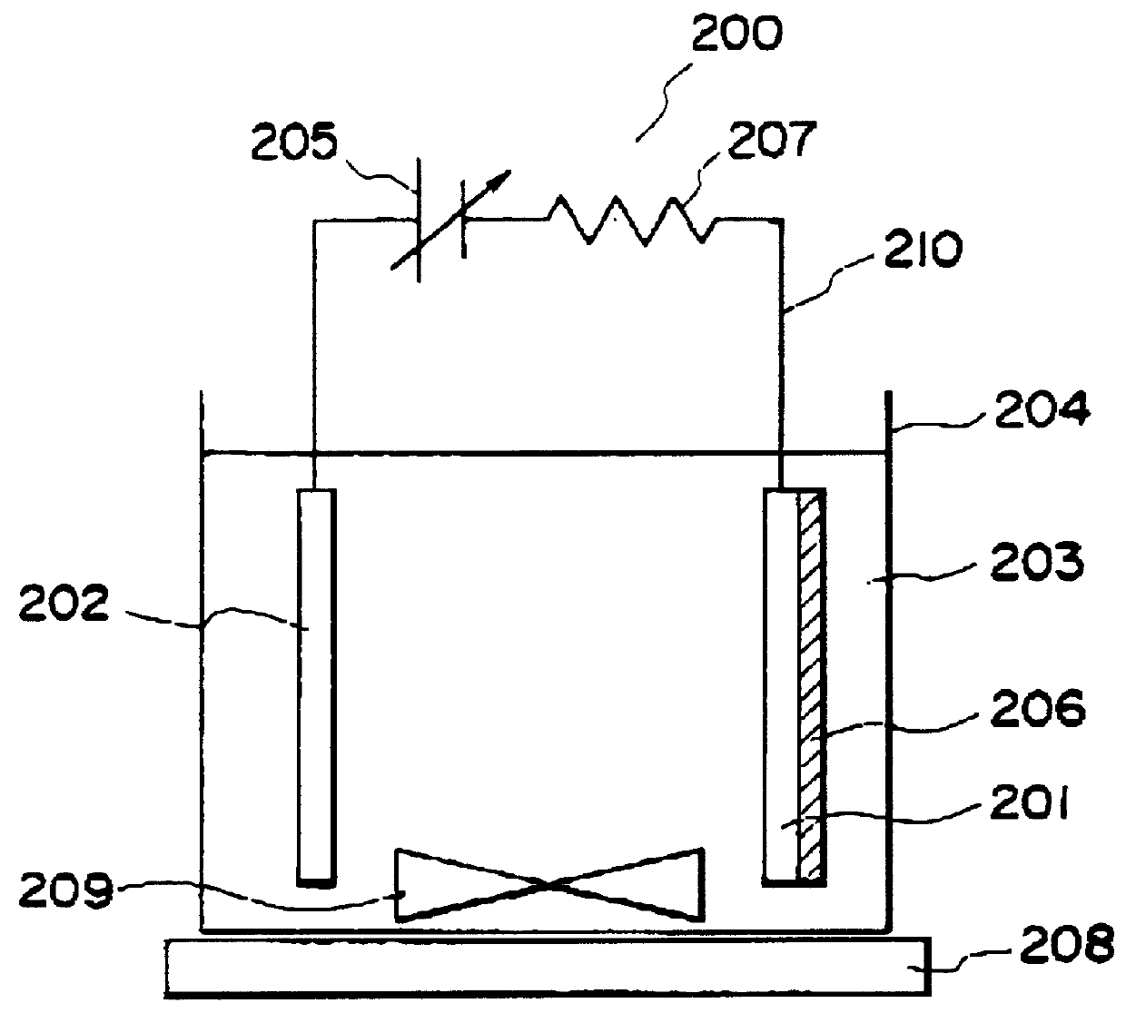
On the intermediate zinc oxide layer, a 1.75 .mu.m-thick zinc oxide layer was formed under conditions shown in Table 3 by using a continuous film-forming and etching apparatus (Roll-to-Roll scheme) as shown in FIG. 4A.

Referring to FIG. 4A, in the apparatus, a flexible continuous sheet of stainless steel 401 to which backside an insulating tape (sheet) was supplied (not shown) was supplied from a lead-on (delivery) roller 433 about which the continuous stainless steel sheet was wound and was conveyed by conveyance rollers 432 via respective tanks to a wind-up (take-up) roller 434 to which the steel was wound up in a rolled (coiled) shape. The respective rollers had a diameter of at least 40 cm...

example 4

A photo-electricity generating device was prepared and evaluated in the same manner as in Example 1 except that a zinc oxide layer consisting of an upper layer and a lower layer was formed under conditions shown in Table 4 so that the current density and solute (zinc nitrate providing nitrate and zinc ions) concentration for the upper layer were set to be lower than those for the lower layer.

As a result of the evaluation, the resultant photo-electricity generating device was found to exhibit better performances similarly as in the device of Example 1.


PUM

PropertyMeasurementUnit
thicknessaaaaaaaaaa
thicknessaaaaaaaaaa
thicknessaaaaaaaaaa

Abstract

A photo-electricity generating device is produced through the steps of: immersing an electrode and an electroconductive substrate in an aqueous solution comprising nitrate ions and zinc ions, supplying a current passing through a gap between the electrode and the electroconductive substrate to form a first zinc oxide layer on the electroconductive substrate, etching the first zinc oxide layer, and forming a semiconductor layer on the zinc oxide layer. The zinc oxide layer may preferably be formed in two zinc oxide layers under different electrudeposition conditions. In this case, the etching step may preferably be performed between steps for forming these zinc oxide layers. The zinc oxide layer is provided with an unevenness at its surface suitable for constituting a light-confining layer of a resultant photo-electricity generating device.

Description

FIELD OF THE INVENTION AND RELATED ARTThe present invention relates to a process for producing an photo-electricity generating device including an zinc oxide layer formed through electrodeposition (electrolytic deposition).In a process for producing an electro-electricity generating device, there has been known that a reflection layer of, e.g., metal is formed on the back side of an semiconductor layer in order to improve a light-collection efficiency of the photo-electricity generating device on a long wavelength. Further, there has also been known that a transparent electroconductive layer having an unevenness is formed between the reflection layer and the semiconductor layer to obtain a light-confining (optical confinement) effect that an optical distance (optical path) of reflected light is elongated or lengthened to obtain an effect of suppressing an excessive current flowing at the time of an occurrence of a shunt passing. As the transparent elebtroconductive layer, there has ...

Claims


Application Information

Patent Timeline
Patent Type & Authority Patents(United States)
IPC IPC(8): C25D9/08C25D9/00C25D5/48
CPCC25D5/48C25D9/08
Inventor SANO, MASAFUMIKARIYA, TOSHIMITSU
Owner CANON KK
Why Eureka
Try Eureka