Electrostatic method and means for removing contaminants from gases

Inactive Publication Date: 2001-05-01
PULSATRON TECH CORP
View PDF12 Cites 89 Cited by
  • Summary
  • Abstract
  • Description
  • Claims
  • Application Information

AI Technical Summary

Benefits of technology

As will be explained in detail below, under certain conditions, the field produced by DC voltage in the coronating current will not support the accumulation of highly charged metastable intermediaries in an atmosphere containing noble gases. When electrical breakdown occurs, the ensuing arcing between the coronating electrode and the wall of the reaction chamber impedes, and may effectively counteract, the intended reaction. To accommodate these situations, the sub

Problems solved by technology

Catalytic converters are usually specific to a particular contaminant and may in fact be impaired or even destroyed by combinations of contaminants or contaminants and ambient conditions.
Thermal systems, from simple incinerators to esoteric plasma furnaces, tend to be highly inefficient, employing large amounts of fuel or electrical energy-producing resources to heat waste stream temperatures to their operational levels.
Commonly, they produce substantial quantities of ash and other solid, frequently hazardous, byproducts the removal and disposal of which in themselves pose a variety of logistical and ecological problems.
Principal among these is their high degree of unpredictable sensitivity to temperature, humidity, pollutant concentration, and flow rate.
As will be shown, the results demonstrate that, properly utilized, inert gases can profoundly enhance the electrochemical process and substantially and

Method used


Image

  • Electrostatic method and means for removing contaminants from gases
  • Electrostatic method and means for removing contaminants from gases
  • Electrostatic method and means for removing contaminants from gases

Examples


Embodiment Construction

The Preferred Embodiment

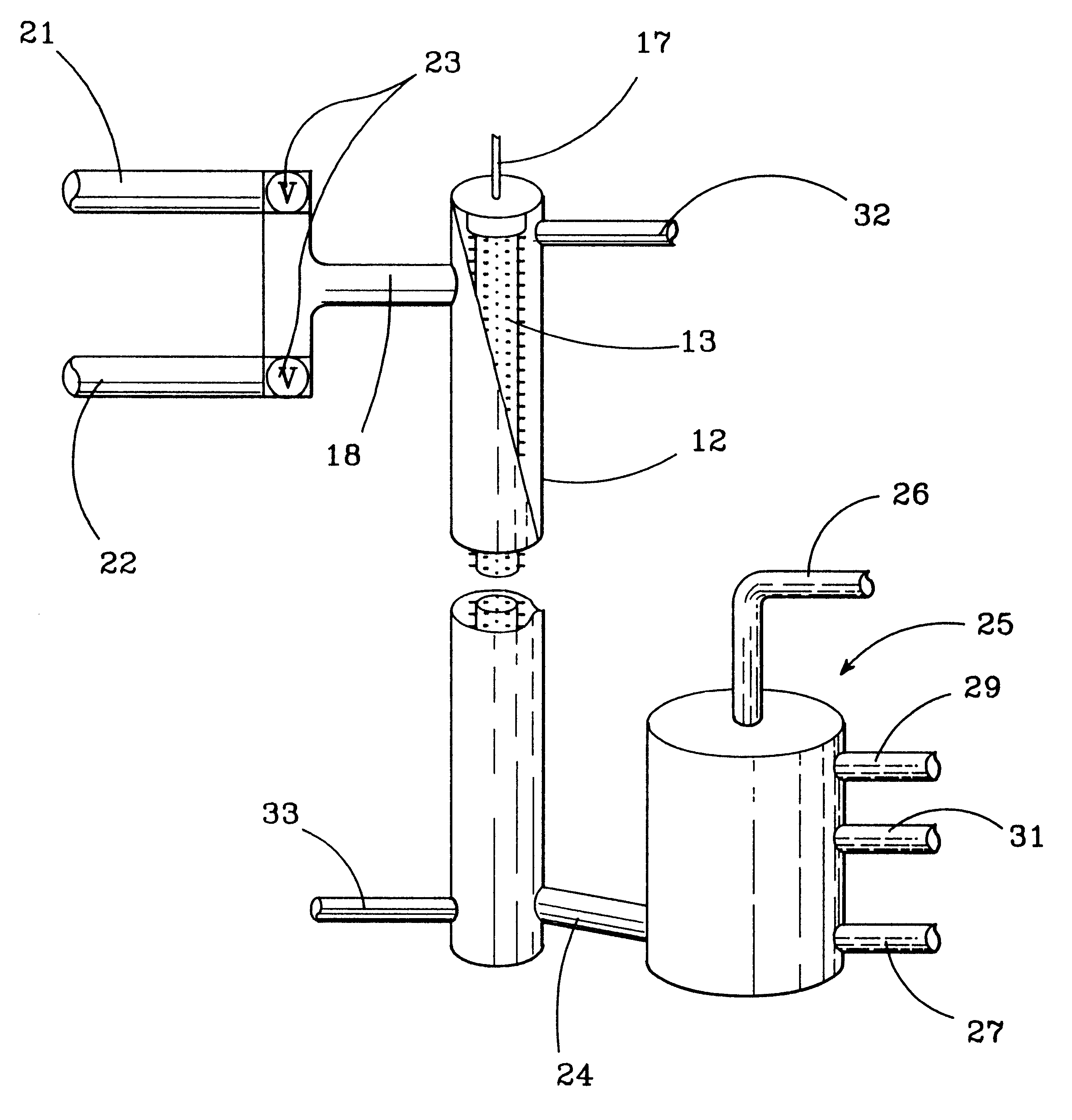
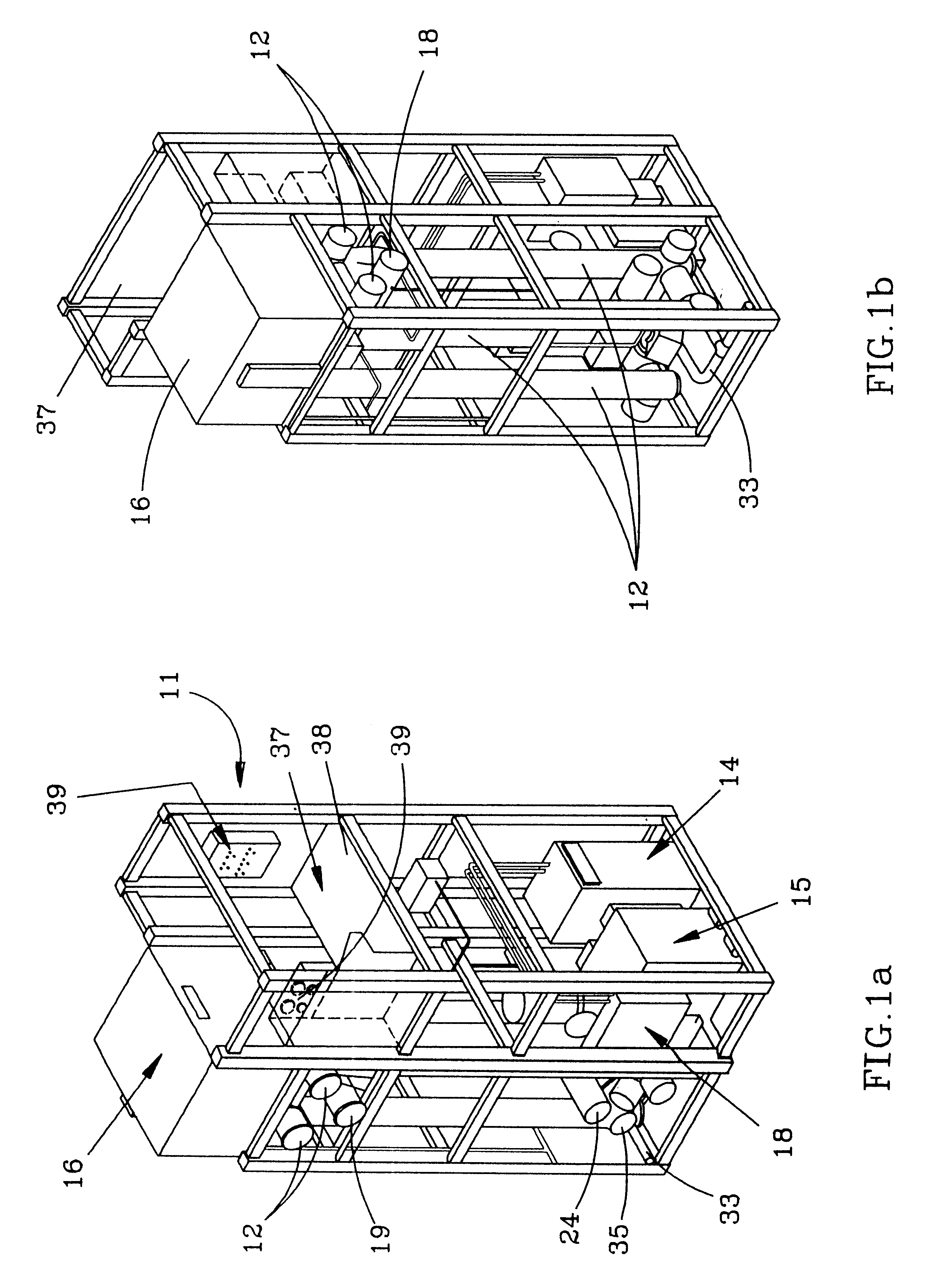
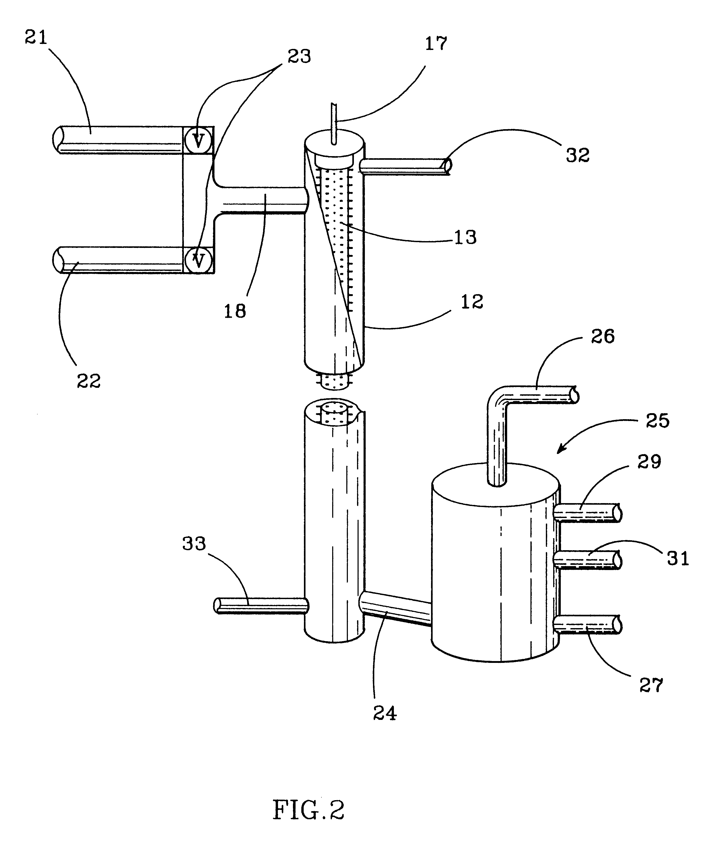
Referring to FIGS. 1a, 1b, and 2, an operational installation 11 of an electrostatic precipitator in accordance with the subject invention is fabricated as a unitary structure occupying a space that measures approximately 12'.times.12'.times.22'. The structure contains four grounded cylindrical corona electric reaction chambers 12. Each chamber 12 is about 12' long and 12" in diameter and contains a coronating electrode 13 mounted coaxially with its central axis. A variable transformer 14 and transformer rectifier 15 feed a high voltage pulse generator 16 (actually a pair of generators) connected in parallel to the leads 17 of electrodes 13. A main power switch panel 18 provides power for the installation 11.

At the upper end of each reaction chamber 12, an inlet 18 is provided for attachment to a source 21 of contaminated gas, such as the waste stream from a plasma furnace or industrial incinerator system or the exhaust from a manufacturing facility, and a so...


PUM


Abstract

An electrical apparatus includes a reaction chamber. A stream of contaminated gasses flows through the chamber. An elongated coronating electrode is positioned in the reaction chamber for producing a corona discharge within the chamber. A multi-stage Fitch generator connected to the electrode produces a high level, rapidly pulsating voltage in the electrode. Controlled amounts of an inert gas or inert gas-air mixture are combined with the contaminated gases to provide a high concentration of inert gas in the reaction chamber. In the inert gas-enriched atmosphere, the pulsating corona discharge produces a high concentration of metastable intermediates that greatly increase the rate of chemical conversion of the contaminants. Switching circuitry allows the pulsating voltage output of the Fitch generator to be superimposed on a constant direct current voltage in the electrode, setting up an electrostatic field in the reaction chamber for removing conversion byproducts from the gas stream.

Description

1. Field of the InventionThe present invention relates to the electrostatic removal of contaminants from air and industrial and domestic gases, and more particularly to the use of a very short duration, high voltage pulsating electrical corona discharge for that purpose. Still more particularly, it provides an improved method and highly effective apparatus for enhancing the capacity of the pulsed corona to modify the molecular structure of, and destroy, pollutants.2. Prior ArtPrior art systems for removing or destroying pollutants fall generally into one of three categories. One type utilizes catalysts to achieve the desired result. A second employs thermal technology. A third involves some form of electrical discharge in a reaction chamber. Depending on the pollutant and the operative conditions, each has its advantages and deficiencies. For the removal of contaminants from fluids, and particularly gases, the first two suffer from a number of inherent disadvantages. Catalytic conve...

Claims


Application Information

Patent Timeline
IPC IPC(8): B01D53/34
CPCB01D53/34B01D2259/818Y10S323/903
Inventor SHVEDCHIKOV, ADOLF PAVLOVICHPONIZOVSKY, ALEKSANDER ZALMANOVICHPONIZOVSKY, LAZAR ZALMANOVICHKRYUTCHKOV, SERGEI PETROVICHSTAROBINSKY, VLADIMIR YAKOVLEVICH
Owner PULSATRON TECH CORP
Why Eureka
Try Eureka