
Oxygen separation method using a mixed conducting cubic perovskite ceramic ion transport membrane

a technology of cubic perovskite ceramic and ion transport membrane, which is applied in the direction of catalyst activation/preparation, chemical/physical processes, inorganic chemistry, etc., can solve the problems of affecting the stability of the membrane and other components of the reactor, and the perovskite with a hexagonal crystalline structure are not effective for oxygen transpor

Inactive Publication Date: 2001-05-22
PRAXAIR TECH INC
View PDF6 Cites 17 Cited by
  • Summary
  • Abstract
  • Description
  • Claims
  • Application Information

AI Technical Summary

Benefits of technology

A second object of the invention is to provide the ceramic material with enhanced mechanical stability to avoid cracking under stress. Such stresses may be imposed due to temperature differences between different portions of the membrane element as well as due to a higher concentration of oxygen on the cathode side of the membrane than on the anode side during start-up.

Problems solved by technology

Perovskites with a hexagonal crystalline structure are not effective for oxygen transport.
Operating at such high temperatures is detrimental to the stability of the membrane as well as the other components of the reactor.

Method used


Image

  • Oxygen separation method using a mixed conducting cubic perovskite ceramic ion transport membrane
  • Oxygen separation method using a mixed conducting cubic perovskite ceramic ion transport membrane

Examples


example 1

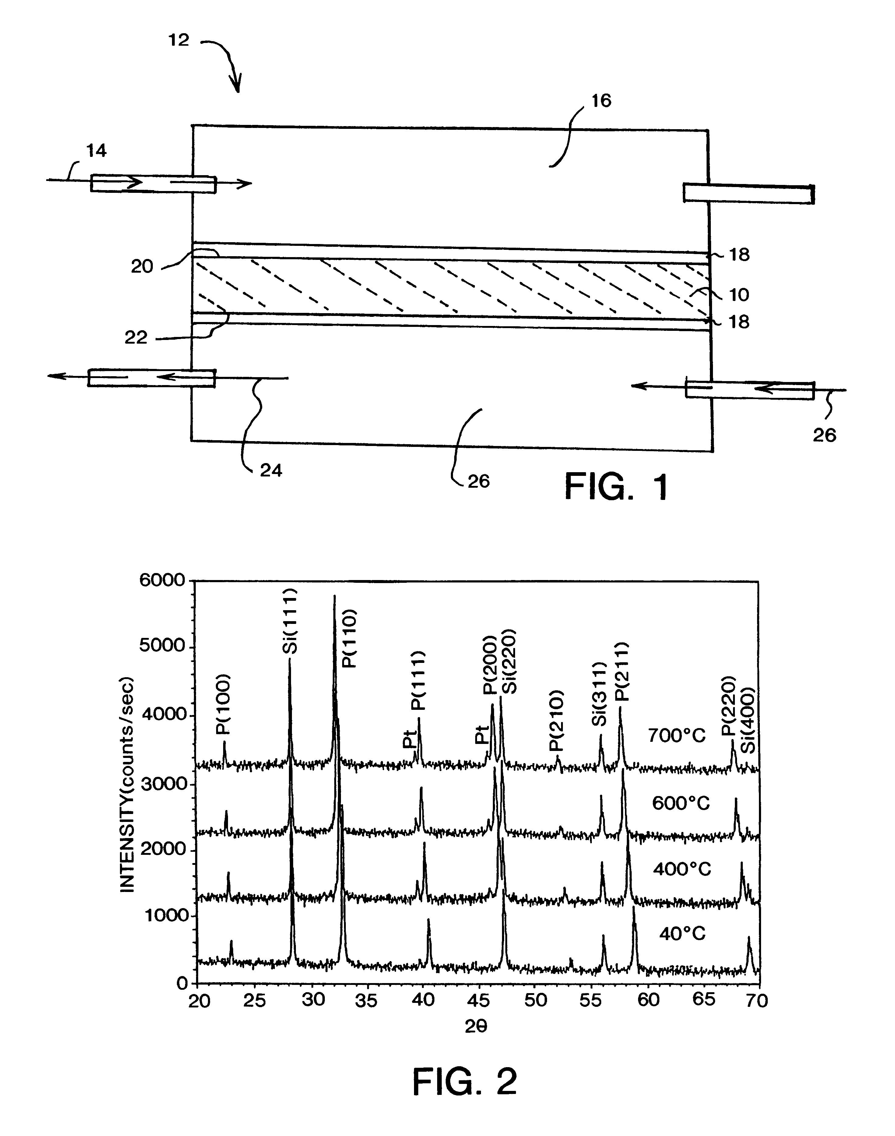
X-ray diffraction (XRD) analysis of a ceramic pellet formed in accordance with the first embodiment described above, was performed using a Scintag (manufactured by Scintag, Inc. of Cupertino, Calif.) diffractometer with a hot stage attachment to analyze phase development at various temperatures. As illustrated in FIG. 2, the specimen maintained a cubic structure without phase transformation at all temperatures between 40.degree. C. and 700.degree. C. The silicon and platinum peaks in FIG. 2 are from an internal standard and sample holder, respectively.

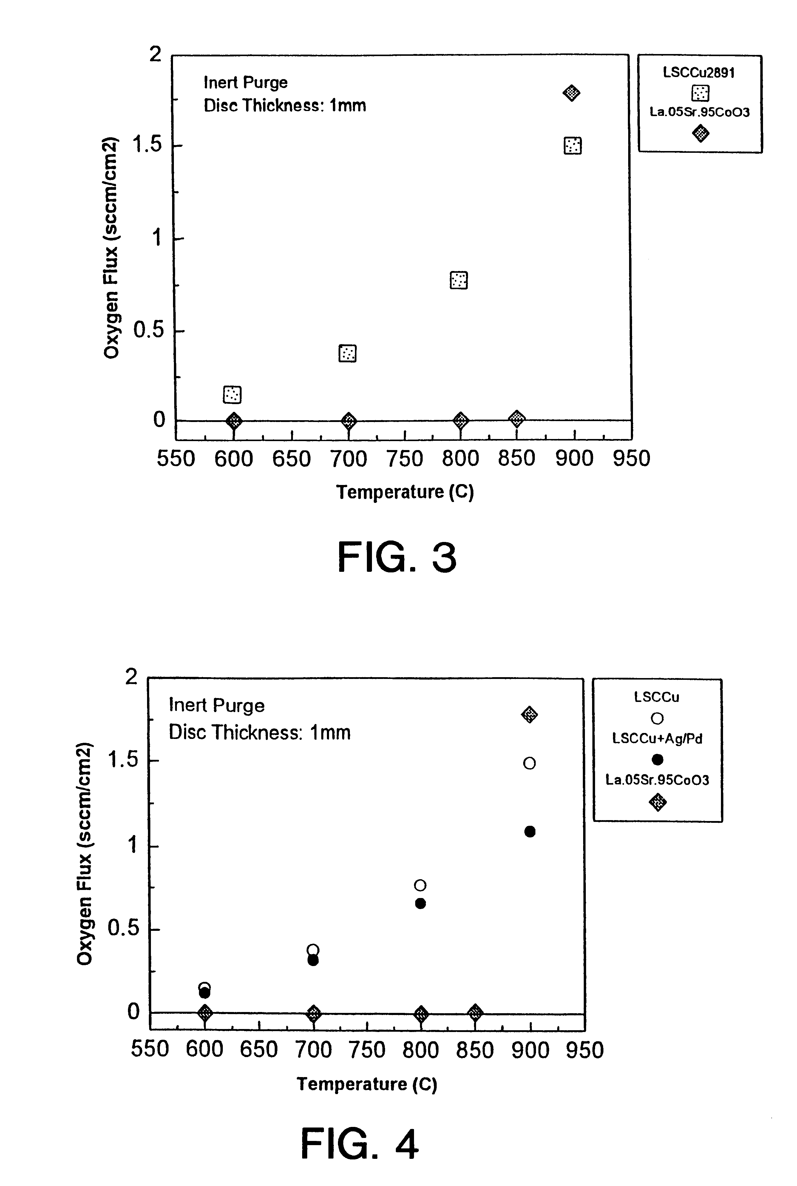
The oxygen permeation rate of the sample was measured using a sintered disc having a thickness of 1.0 mm sealed in an alumina test cell with a silver paste. Permeation testing was conducted as a function of temperature using as a feed gas 20%, by volume, of oxygen, in nitrogen. Introduction of the feed gas was preceded by a helium purge.

A Hewlett Packard 5890 gas chromatograph (manufactured by Hewlett Packard Company of Wilmington, Del...

example 2

A one mm thick disc of the composition disclosed as the second embodiment above, was sealed in an alumina test cell with silver paste and permeation testing conducted as above. Table 4 records the detected oxygen flux.

FIG. 4 compares the oxygen flux achieved by the ceramic material formed in accordance with embodiment 2 with the respective oxygen flux of the ceramic material formed in accordance with embodiment 1 and the prior art ceramic material described above. While the addition of the metallic phase reduces the oxygen flux slightly, an oxygen flux is detected at temperatures as low as 600.degree. C. and a commercially useful oxygen flux is achieved at temperatures as low as 800.degree. C. Significantly, upon cooling, the sample remained intact without any cracking.


PUM

PropertyMeasurementUnit
temperatureaaaaaaaaaa

Abstract

A ceramic membrane element for an oxygen separator is formed from a ceramic material represented by the structure:whereA is a lanthanide element;A' is a suitable lanthanide element dopant;B is selected from the group consisting of titanium, vanadium, chromium, manganese, iron, cobalt, nickel, zinc and mixtures thereof;B' is copper;x is between 0.4 and 0.8;y is between 0.1 and 0.9; andz is>0 (and determined by stoichiometry).When B includes cobalt in an amount greater than 0.1, the included iron content is less than 0.05.The membrane element selectively transports oxygen ions therethrough at a relatively low temperature, with a flux detected at about 600° C. This enables the oxygen separator to be operated at lower temperatures than convention separators that frequently have operating temperatures in excess of 900° C. Mechanical stability may be enhanced by the addition of a second phase to the ceramic.

Description

This invention relates to an oxygen separation method using ceramic compositions useful as solid electrolyte ion transport membranes. More particularly, the invention relates to a perovskite structure that contains the oxides of two lanthanides and two transition metals. The composition is oxygen deficient and maintains a cubic structure over a wide temperature range.The separation of oxygen from an oxygen containing gaseous stream is a process step in a number of commercially significant manufacturing operations. One method of oxygen separation utilizes a mixed conductor ceramic material. Oxygen ions and electrons are selectively transported through the non-porous ceramic membrane element that is impervious to other species. Suitable ceramics include mixed conductor perovskites and dual phase metal--metal oxide combinations. Exemplary ceramic compositions are disclosed in U.S. Pat. Nos. 5,702,959 (Mazanec, et al.), 5,712,220 (Carolan, et al.) and 5,733,435 (Prasad, et al.), all of ...

Claims


Application Information

Patent Timeline
Patent Type & Authority Patents(United States)
IPC IPC(8): B01D61/24B01D61/30B01D63/02B01D71/00B01D65/00B01D71/02B01J35/06B01J35/00C04B38/00C04B35/50C01B13/02C04B35/01H01M4/86H01M8/12B01J37/00B01J37/02B01D53/22C01G51/00C04B35/00
CPCB01D53/228B01D61/30B01D63/02B01D65/00B01D67/0041B01D67/0051B01D69/145B01D71/02B01D71/022B01D71/024B01J35/0006B01J35/0033B01J35/065C01B13/0255C04B35/01C04B35/50C04B38/00H01M4/8621H01M4/9066C04B35/45B01D2323/12B01D2325/26B01J37/0244C01B2210/0046C04B2111/00801Y02E60/50B01J35/19B01J35/59B01J35/33B01D71/0213B01D67/00411B01D71/02231B01D71/0271
Inventor ANDERSON, HARLAN U.SPRENKLE, VINCENTKAUS, INGEBORGCHEN, CHIEH-CHENG
Owner PRAXAIR TECH INC
Learn More