Method of forming catalyst layer for fuel cell

a fuel cell and catalyst technology, applied in the field of forming catalyst layers for fuel cells, can solve the problems of reducing catalyst utilization efficiency, electrode use, and low catalyst utilization efficiency compared to liquid electroly

Inactive Publication Date: 2002-02-05
SAMSUNG SDI CO LTD
View PDF3 Cites 26 Cited by
  • Summary
  • Abstract
  • Description
  • Claims
  • Application Information

AI Technical Summary

Problems solved by technology

Since the PEM fuel cell uses a solid polymer as an electrolyte, the boundary between the electrode and the electrolyte is two-dimensional, which reduces the catalyst utilizing efficiency, compared to a liquid electrolyte.
Here, since the oxidation/reduction reaction of a gaseous fuel in the presence of a catalyst occurs only at the boundary between the electrode and the electrolyte, the catalyst utilizing efficiency is very low.
However, in this case, due to high costs, the thus-formed electrode is used only for special purposes.
Thus, Pt in the catalyst layer may be covered by PTFE, which lowers the catalyst utilizing efficiency.
Also, since a sufficient catalyst loading cannot be attained by performing coating only once, the coating step must be repeated twi

Method used


Image

  • Method of forming catalyst layer for fuel cell
  • Method of forming catalyst layer for fuel cell
  • Method of forming catalyst layer for fuel cell

Examples


example

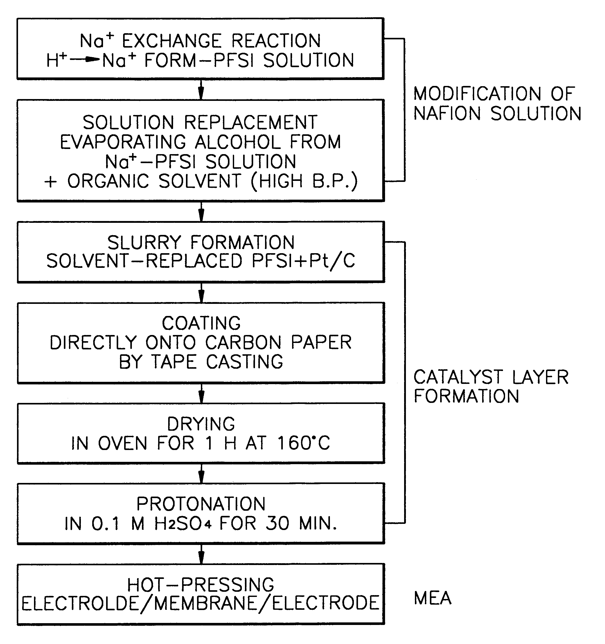
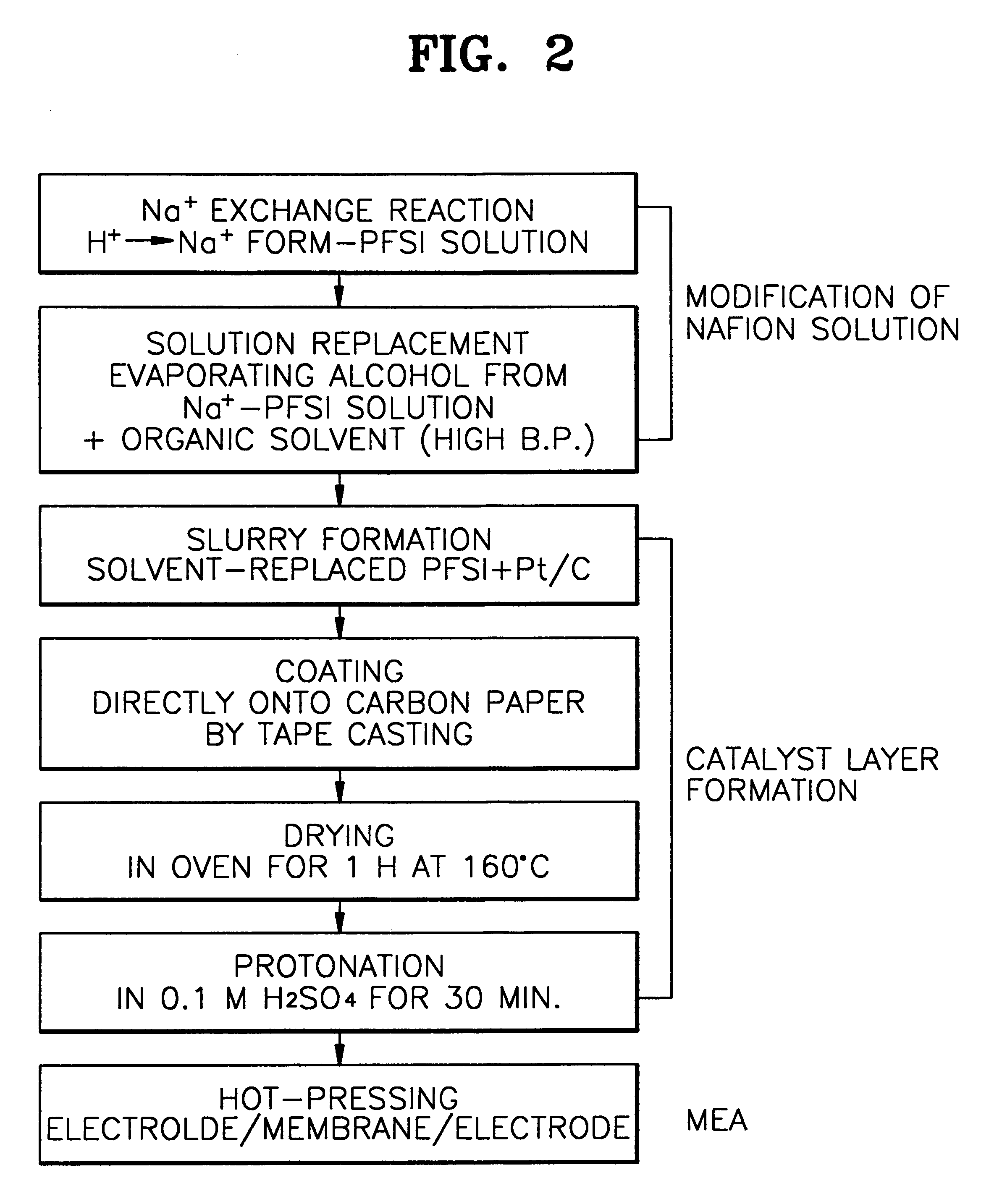
To 10 g of a perfluorosulfonate solution (5% by weight, Aldrich Chemical Company, Inc), aqueous NaOH solution was added in the same equivalent ratio and stirred at room temperature for one night to convert the PFSI in the solution to a Na+form. 9.5 g of ethylene glycol was added to the thus-mixed solution and heated in an oven or an oil bath at approximately 85.degree. C. for 12 hours to remove alcohol components remaining in the mixed solution. Pt / C (20% Pt by weight, available from E-Tek Inc. under the trademark of Vulcan XC72R) was mixed in a weight ratio of 1:2, based on the weight of the PFSI in the mixed solution, and uniformly mixed using a mixer such as a ball mill to obtain a mixture in the form of a slurry. Here, the viscosity of the slurry was 3000 cp.

The slurry mixture was coated on the backing layer using a carbon paper available from E-Tek Inc., which was waterproofed with 20 wt % tetrafluoroethylene-hexafluoropropylene copolymer available from E.I. DuPont under the tr...


PUM


Abstract

A method for preparing a slurry for forming a catalyst layer of a PEM fuel cell electrode and a method for fabricating the PEM fuel cell produced thereby are provided. The method for preparing a slurry for forming a catalyst layer of a proton exchange membrane (PEM) fuel cell according to the present invention comprises the steps of (a) adding an MOH solution to a perfluorosulfonate ionomer (PFSI) solution to convert PFSI in the PFSI solution into an M+ form-PFSI solution, wherein M is an alkaline metal selected from the group consisting of Li, Na and K; (b) adding an organic polar solvent having a higher boiling point than that of alcohol remaining in the PFSI solution to a mixed solution obtained in step (a) and heating the mixture at a temperature range of the boiling point of the alcohol to 20° C. higher than the boiling point to remove the remaining alcohol to obtain a pretreated PFSI solution; and (c) mixing the pretreated PFSI solution with Pt/C to form a slurry for forming a catalyst layer of a PEM fuel cell. Since processing stability is improved and the slurry can be easily prepared, Pt loading greater than a conventional level can be achieved by a single coating step by preventing a Pt catalyst from penetrating into a backing layer, the electrode characteristics are improved. Also, mass production of the PEM fuel cells is possible.

Description

This application claims priority under 35 U.S.C. .sctn..sctn.119 and / or 365 to Korean Patent Applications No. 98-15991 filed May 4, 1998, and No. 98-60009 filed Dec. 29, 1998; the entire contents of which are hereby incorporated by reference.1. Field of the InventionThe present invention relates to a proton exchange membrane (PEM) fuel cell, and more particularly, to a method for preparing a slurry for forming a catalyst layer of a PEM fuel cell electrode having an improved processing stability and power output characteristics, a method for fabricating membrane / electrode assembly (MEA) for the PEM fuel cell and a PEM fuel cell produced by the MEA fabricating method.2. Description of the Related ArtA proton exchange membrane (PEM) fuel cell is a potential clean energy source which can replace fossil fuels and has a high current density and energy conversion capability. Also, the PEM fuel cell is operable at room temperature and can be miniaturized and hermetically fabricated, and thu...

Claims


Application Information

Patent Timeline
IPC IPC(8): H01M4/88H01M8/10H01M4/92H01M4/90
CPCH01M4/8807H01M4/8828H01M4/8882H01M4/926H01M8/1004H01M4/8896Y02E60/522H01M2300/0082Y02P70/50Y02E60/50
Inventor LIM, CHANCHANG, HYUK
Owner SAMSUNG SDI CO LTD
Why Eureka
Try Eureka