
Rapid production of engineering tools and hollow bodies by integration of electroforming and solid freeform fabrication

a technology of electroforming and freeform fabrication, which is applied in the direction of manufacturing tools, foundry patterns, moulding apparatus, etc., can solve the problems of difficult separation of electroforming from master, difficulty increases, and development of electroforming is the manufacturing of master, so as to minimize stress on electroformed materials during burnout, and the effect of rapid prototyping design and manufacturing

Inactive Publication Date: 2002-06-25
NEW JERSEY INSTITUTE OF TECHNOLOGY
View PDF22 Cites 59 Cited by
  • Summary
  • Abstract
  • Description
  • Claims
  • Application Information

AI Technical Summary

Benefits of technology

It is an advantage of the present invention that the shape of the rapid prototyping master is maintained during electroform deposition and the shape of the electroform material is maintained during burn-out.

Problems solved by technology

Electroforming can be used to reproduce the reversed shell of a wide variety of parts and shapes, the principal limitation being that it must be possible to separate the master from the metal shell, similar to the situation that the molding part must be able to be removed from the mold cavity.
The main obstacle to the development of the electroforming is the manufacturing of the master.
However, separation of the electroform from the master may not be easy and the difficulty increases as the form complexity increases.
Separation of RP master by mechanical pull-off has been found impractical, however, since extreme care and skills are required during the pulling off process in order not to damage the metal shell.
The pulling force may break the master thus leaving some master relic in the metal shell, especially when the master is brittle and intricate in shape.
Dissolving the RP master in a chemical solution to separate the metal shell by causing delamination of the interface layer may be possible but the time taken may be excessive.
A major problem is that these materials have much higher coefficients of thermal expansion than the electroformed metal.
The use of thermal cycling to separate a polyurethane master from a metal shell has been attempted, but those skilled in such attempts recognize that removal of an SL master is more difficult than removal of a polyurethane part.
This is due to the fact that an SL part is more brittle and tends to fracture during the removal process.
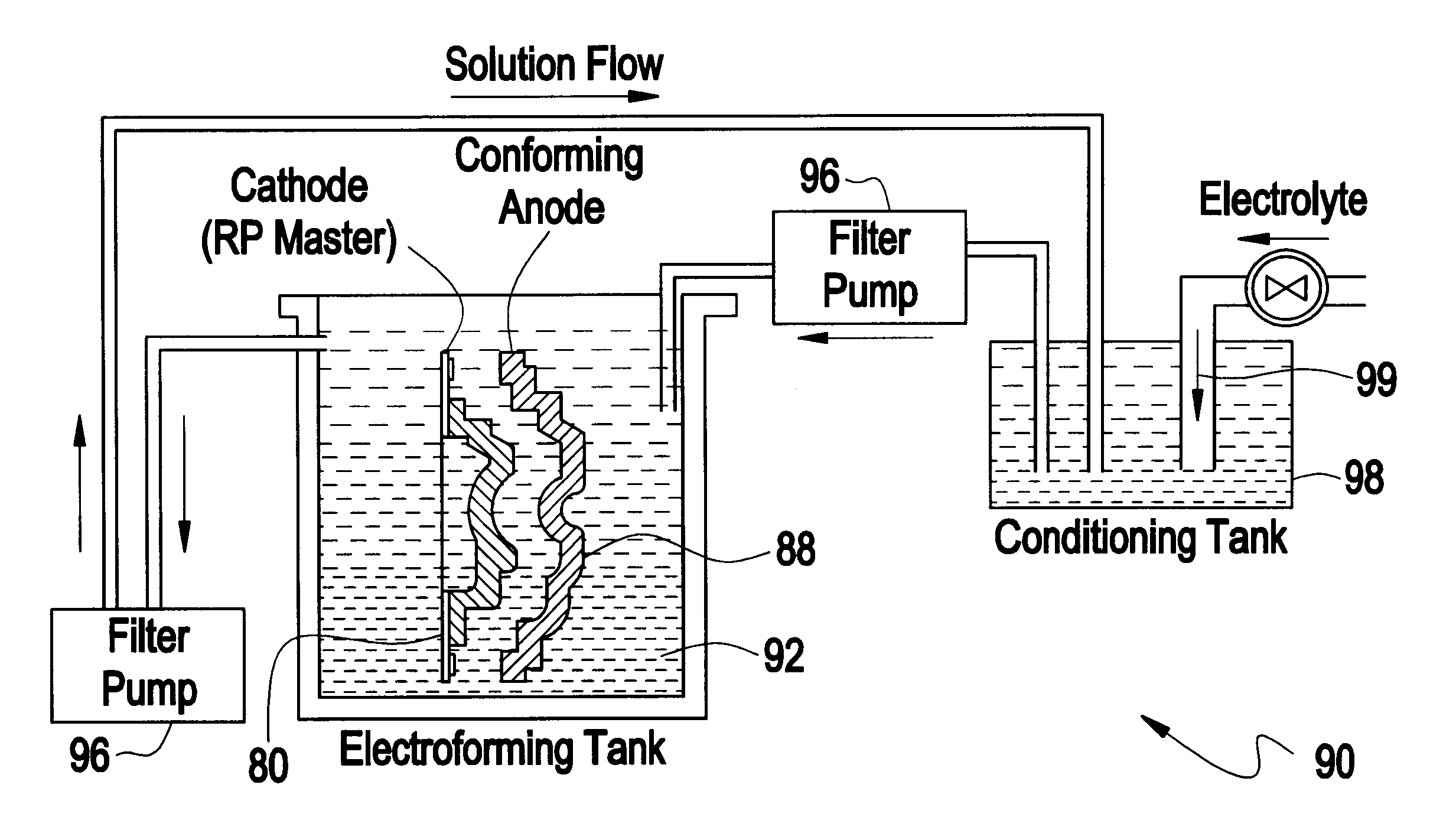
Another shortage of electroforming for making complex tools is the slowness and inefficiency of the electroforming process, due in-part to the non-uniformity of the distribution of the current density between the anode and the cathode.
The uneven distribution of current density results in not only uneven distribution of the electroform but also undesirable distribution of its metallic microstructure.
Furthermore, dendrite or like crystalline formations tend to build up on certain localized areas for a master with complex geometry due to the non-uniformity of current density.
As a consequence, it may take many days for the electroformed metal layer to reach a desired thickness.
However, the undesired unevenness can not be completely eliminated even at a low current density.
Since the timing for the need of such removal is generally difficult to predict, the electroforming process is often constantly monitored or interrupted from time to time in order to take the object out and observe the deposition situation.
Electroforming at a higher current density accelerates the deposition rate, but it worsens the non-uniformity and increases the rate of dendrite buildup.
Thus electroforming without a conformal anode is labor-intensive, time-consuming, energy-consuming, and costly.
Also, it wastes chemicals and other useful resources.
However, making of a conformal anode by machining is also expensive and time consuming.
This is where the designer often finds the greatest challenge: to design the cooling channels so that the plastic in the mold cavity is quickly and evenly cooled.
It is often difficult and expensive to provide cooling to small areas near large accumulations of heat.
Cooling channels conforming the shape of the mold cavity is difficult or impossible to make by machining.

Method used


Image

  • Rapid production of engineering tools and hollow bodies by integration of electroforming and solid freeform fabrication
  • Rapid production of engineering tools and hollow bodies by integration of electroforming and solid freeform fabrication
  • Rapid production of engineering tools and hollow bodies by integration of electroforming and solid freeform fabrication

Examples


example 1

Solid RP Master (SL Master) with Chemical Dissolution Methods.

Experiments were first tried on chemical dissolution of the RP master for separation of electroformed metal from the RP master. The material of the RP master is SL resin (an epoxy resin used for SL RP machine). Acetonic solution is the most powerful chemical solution for dissolving the SL resin so is was used to dissolve the solid SL master after it is nickel electroformed. It was found that dissolving the SL master in this chemical solution to separate the metal shell by causing delamination of the interface layer may be possible but the time taken is very excessive. A nickel electroformed SL part, like the one shown in FIG. 18B, to dissolve the SL master, took five days, but the dissolution of the SL part was just a small portion and the SL master can not be removed. Even using a web structure inside the RP master, the time taken for dissolving the RP master was still not desirable. So other separation approaches were t...

example 2

Solid SL Part with Burnout

After the failure of separation of RP master from metal by chemical dissolution, the idea of burnout of the RP master was tried. A solid SL part, as shown in FIG. 18A, was electroformed with nickel at a plating thickness of 2 mm. Then the SL master was burned at an oven with temperature at 560.degree. C. After two hours, the SL part was completely burnout, but the electroform was deformed significantly. The nickel shell was measured using a Coordinate Measuring Machine (CMM) and compared the data with the original SL part. The following table 3 is data we measured using the dimensions shown in parts A and B of FIG 20. As the data shown, the dimensional deviations are too large to be accepted for molding accuracy requirement after the burnout of the SL master. This is because the thermal stress induced by thermal expansion of the SL master deformed the electroform. If the SL part were larger than this one, the thermal expansion problem would have been more s...

example 3-4

Web Structure Inside the RP Master to Reduce the Thermal Stress

Since it was found that the solid RP master will deform the electroform during the burnout process, a web structure was then tried in the next experiment. SL masters as shown in example 3 (FIGS. 21A-B) and example 4 (FIGS. 22A-B) were built. The thickness of the wall enveloping the web structure is 1 mm. The web structure consists of interconnected hexagons with a side length of 3 mm and skin width of 0.8 mm. The master of example 3 was electroformed with 1 mm thick of copper inside the cavity (for EDM electrode). As the picture shows, the web structure is so weak that the electroforming stress cracked the SL master during the electroforming process. As shown in example 3, the corners of the SL master were cracked. The SL master of example 4 was nickel electroformed with a thickness of 2 mm. The deformation of the webbed SL by electroforming stress was so large that it could be observed visually and did not need to be me...


PUM

PropertyMeasurementUnit
Temperatureaaaaaaaaaa
Densityaaaaaaaaaa
Pressureaaaaaaaaaa

Abstract

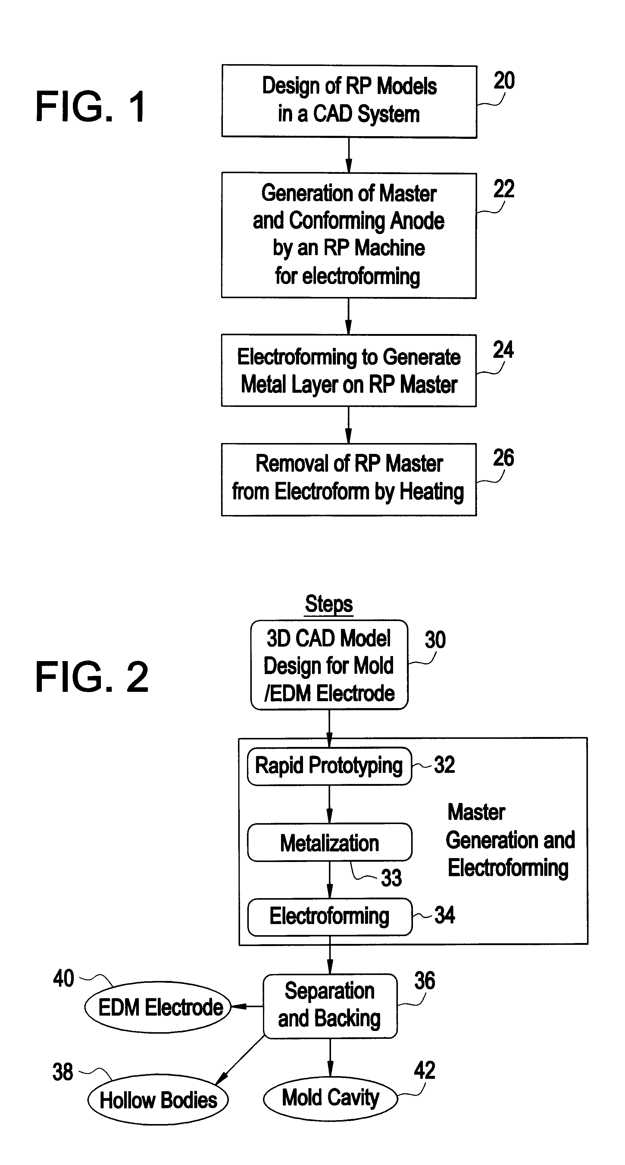
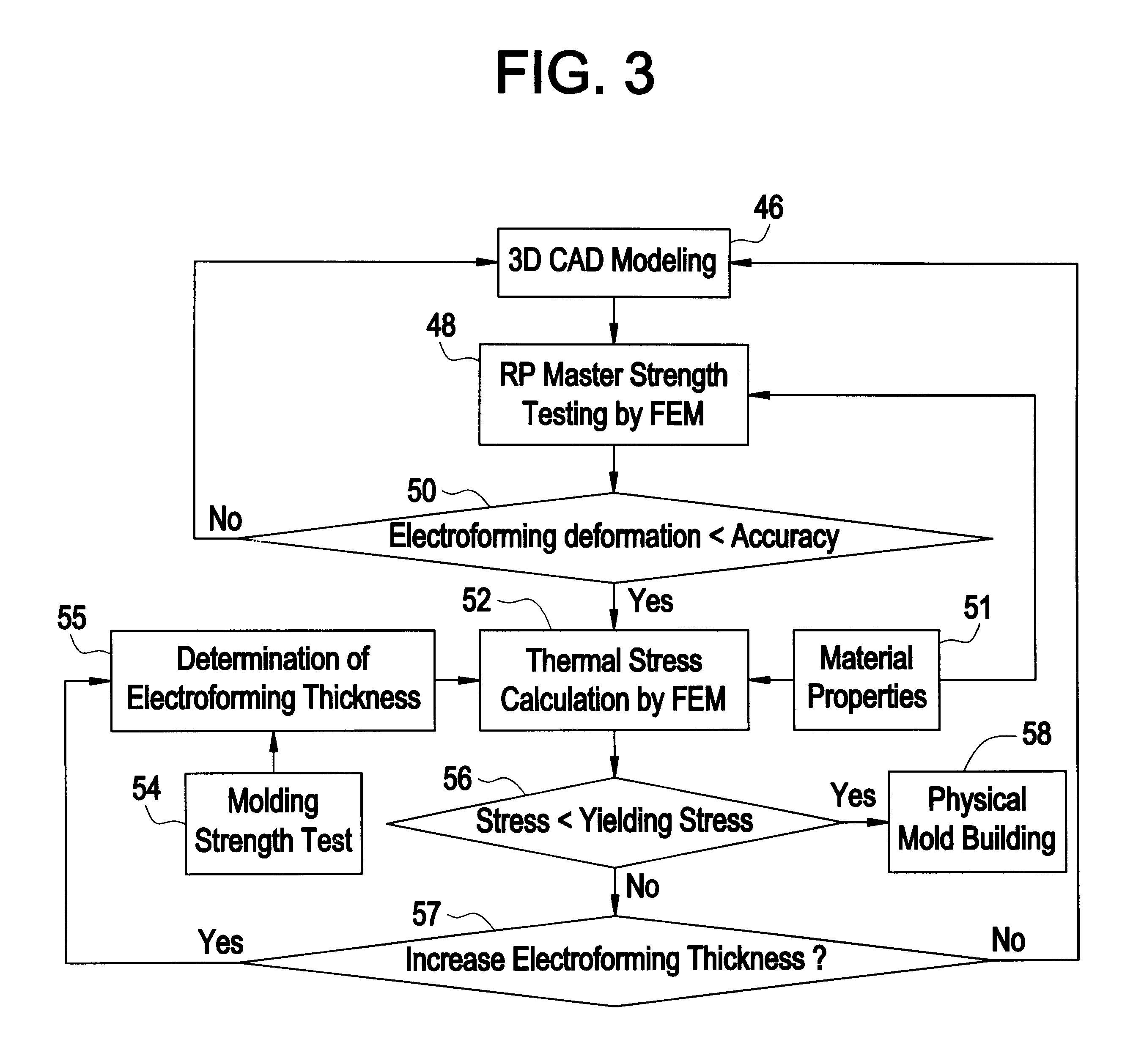
This invention describes a rapid tooling process that integrates solid freeform fabrication (SFF) with electroforming to produce metal tools including molds, dies, and electrical discharge machining (EDM) electrodes. An SFF part is metalized by electroless plating and then placed in an electroplating solution, where metal is deposited upon the part by electrolysis. When the desired thickness of metal has been reached, the SFF part is removed from the metal shell. The shell is then optionally backed with other materials to form a mold cavity, and EDM electrode, or other desired parts for tooling. Thermomechanical modeling and numerical simulation with finite element analysis (FEA) is used to determine the geometry of the SFF part and the electroform thickness for minimizing the manufacturing time and cost while satisfy the tooling requirement.

Description

1. Field of the InventionThe present invention relates generally to a solid freeform fabrication and electroforming system, and more particularly to a solid freeform fabrication and electroforming system for use in the production of engineering tools and hollow bodies.2. Description of the Related ArtElectroforming is the use of electrodeposition of metal onto a master to replicate the master in a reversed format to produce a metal shell. The master, which has the required shape, dimension, accuracy and roughness, is sinked into an electrolyte bath as the cathode and is deposited a required layer of metal, normally copper or nickel. If the master is nonconductive, it needs to be metalized before electroforming. The metal shell is separated from the master to form the mold cavity. Electroforming can be used to reproduce the reversed shell of a wide variety of parts and shapes, the principal limitation being that it must be possible to separate the master from the metal shell, similar...

Claims


Application Information

Patent Timeline
IPC IPC(8): C25D1/00C25D1/10B22C9/06B23H1/04B23H1/06B29C67/00
CPCB22C9/061B23H1/04B23H1/06C25D1/02C25D1/00C25D1/10B29C67/0051B33Y80/00
Inventor YANG, BOLEU, MING C.
Owner NEW JERSEY INSTITUTE OF TECHNOLOGY
Learn More