Magnetohydrodynamic cardiac assist device

Inactive Publication Date: 2002-08-27
CIMEX BIOTECH L C
View PDF27 Cites 28 Cited by
  • Summary
  • Abstract
  • Description
  • Claims
  • Application Information

AI Technical Summary

Benefits of technology

This push-pull action of the MHD pump will allow full blood flow at rest. Once this is in effect, much less invasive procedures can occur to repair coronary blood vessels such as through an endoscope. Through an endoscope the heart may be stopped electrically as is commonly done with open procedures, then coronary artery by-pass surgery procedures may be preformed. The heart would be restarted through an endoscope and the scopes removed.
By not opening the chest, patient's would not have to suffer through the risk, pain, and other problems associated with the current method of by-pass surgery such as: having their sternum cut in half, ribs stretched and broken, massive bleeding, life threatening scar tissue build up on the heart and internal chest cavity, blood pumped outside the body for support, lengthy invasive surgery, massive exposure of the internal chest to infection to just mention a few.
Therefore, it is anticipated that the present invention and system will reduce morbidity and mortality greatly from surgery such as a CABG (coro

Problems solved by technology

Heart assist or left ventricular assist devices (LVADs) are currently large, very invasive (requiring major chest surgery) and represent a significant patient risk.
Typically large and percutaneous devices, they represent a significant surgical risk in their implementation, even if they do provide the necessary coronary assistance.
Removing these devices requires another major bout of surgery with the attendant risks.
Another problem with current LVAD devices is the possibility that the quality of circulation provided by the units, which lack the sophistication of being able to emulate the natural rhythm of the heart, are that they may provide insufficient blood flow to the brain or other organs, to the extent that serious medical consequences arise.
Finally, most of the LVAD pumps currently in use cause some destruction of red blood cells due to the destructive mechanical pumping means utilized.
These machines are for temporary use only, and require extensive thoracic invasion and medication for implementation and use.
Long term use would be fatal, and even short term use can result in hemorrhaging, infection, renal failure, stroke, and other serious effec

Method used


Image

  • Magnetohydrodynamic cardiac assist device
  • Magnetohydrodynamic cardiac assist device
  • Magnetohydrodynamic cardiac assist device

Examples


first embodiment

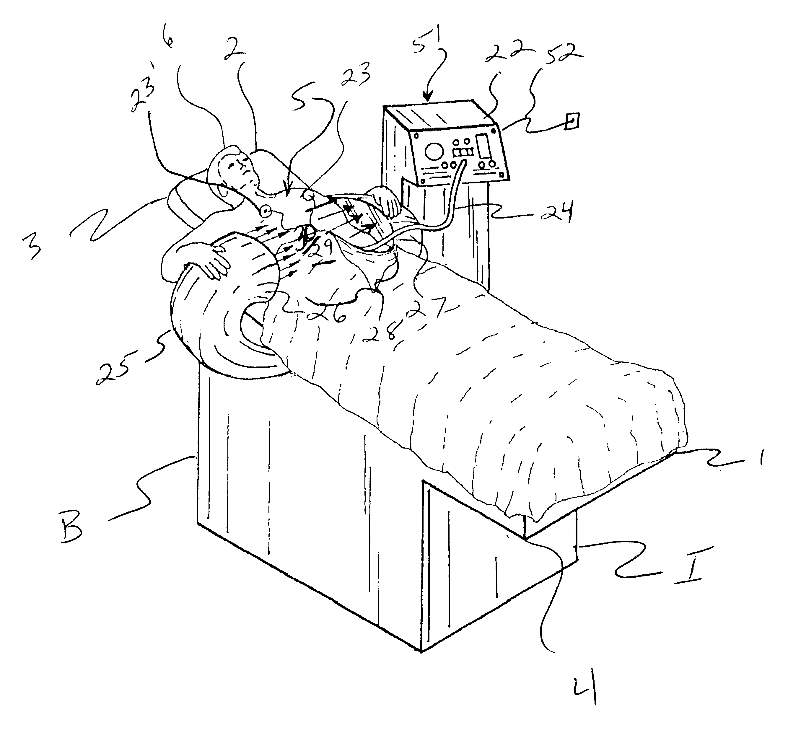
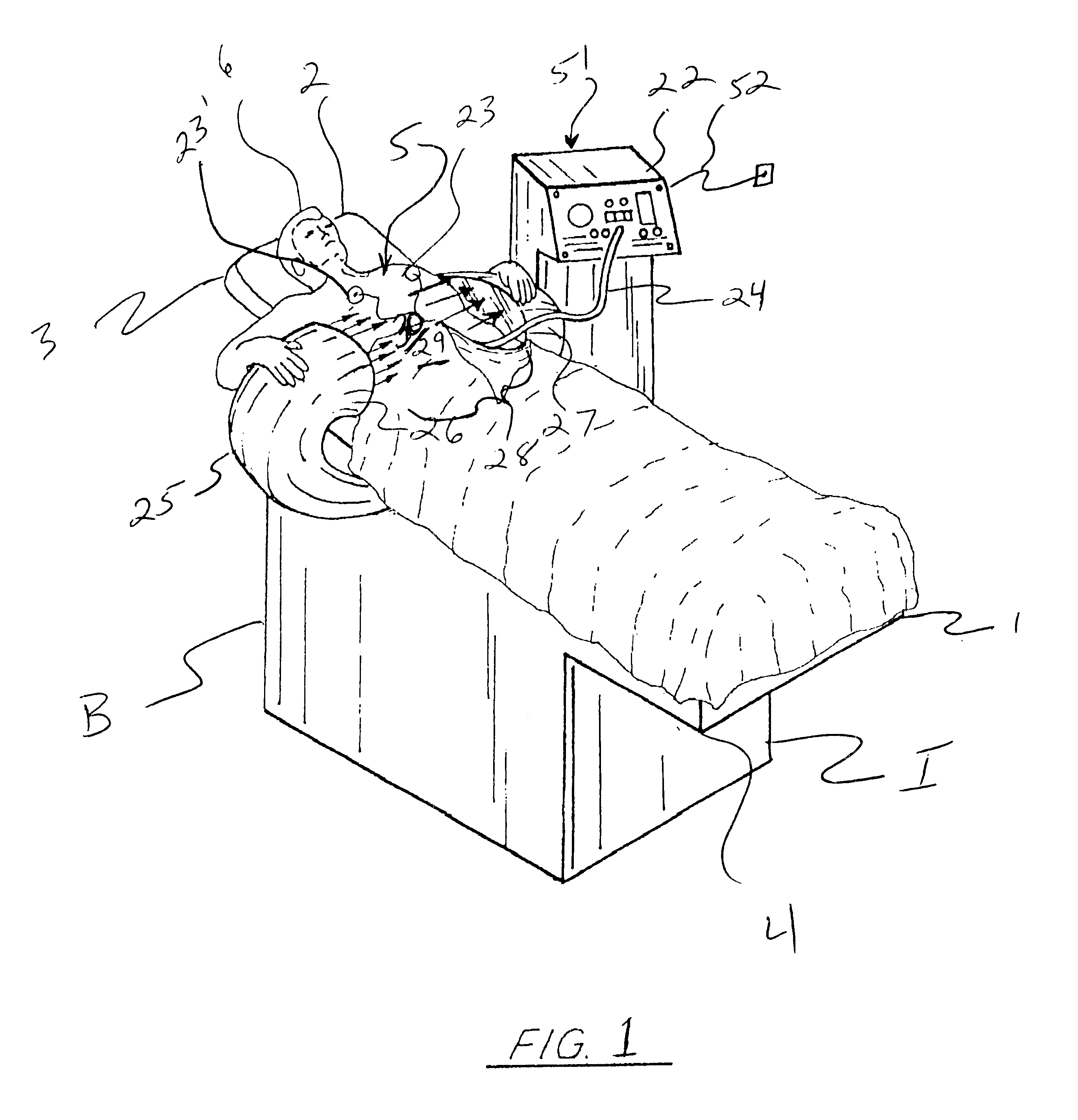
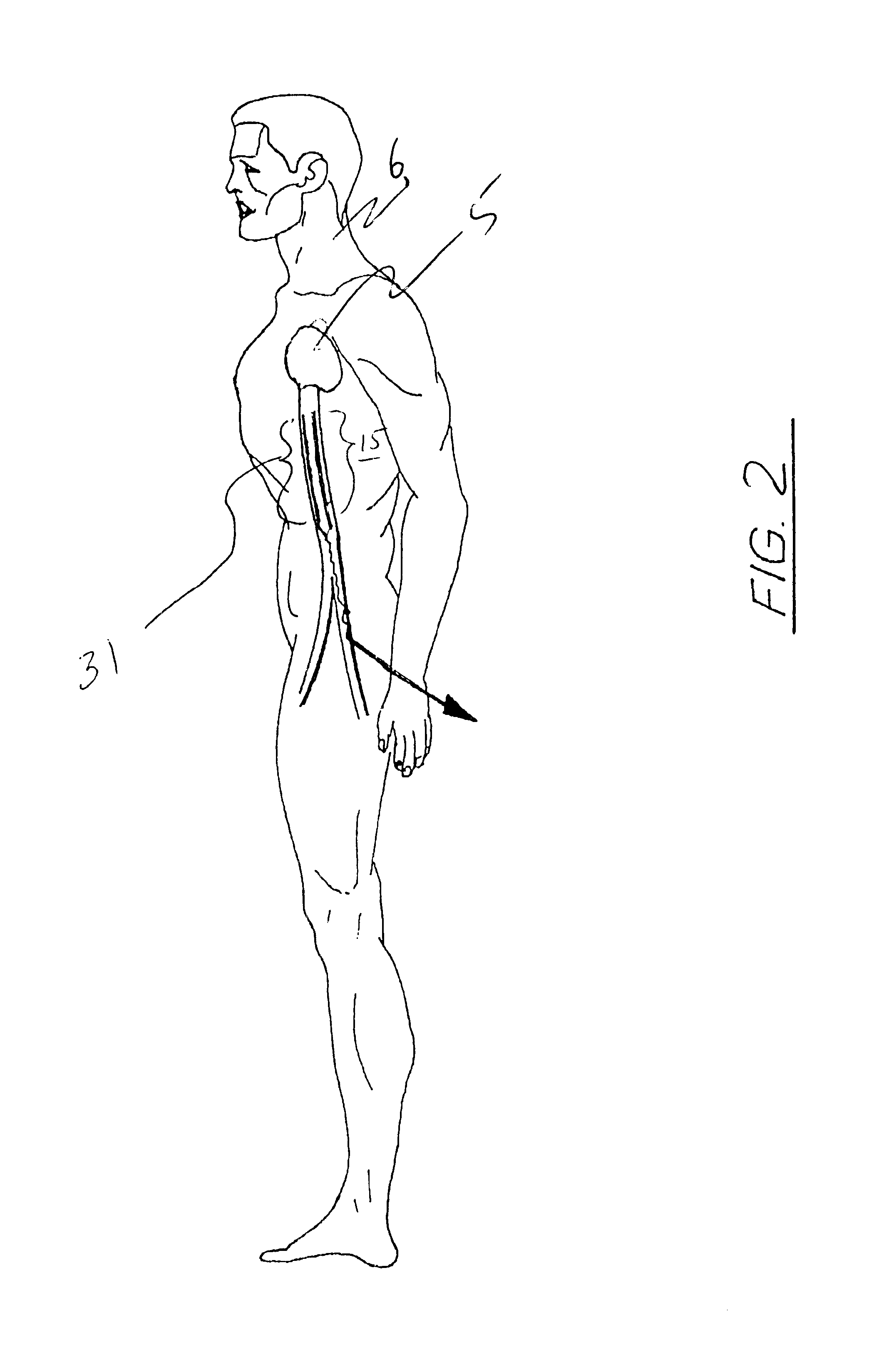
Continuing with FIGS. 1, 2, and 3A, 4A-4C, the present invention comprises an MHD LVAD (left ventricular assist device) configured to provide assistance to the heart 5 of the patient 6 via assist of the left ventricle 8, wherein an aortic electrode assembly 31 is placed into the abdominal aorta 7 of the patient via the femoral artery 9, the placement in similar fashion to the technique employed in facilitating a balloon angioplasty, as will be more fully explained infra.

The aortic electrode assembly 31 comprises a first 13, anterior electrode and a second 14, posterior electrode, the first 13 and second 14 electrodes configured to engage the inner diameter anterior and posterior, or upper and inner walls 7' of the blood vessel in which they are placed, in this case, the aorta 7 (with the patient laying on their back in a generally horizontal position). In the exemplary aortic electrode assembly 31, the first and second electrodes are held in parallel, spaced 33 relationship at oppos...

second embodiment

Continuing with FIGS. 3B, 8, 8A, 8B, and 8C, the invention is configured to provide a minimally invasive by-pass pump for coronary artery by-pass surgery. With the aortic electrode assembly 31 in the abdominal aorta, as discussed supra, providing a magnetohydrodynamic motive force (blood flow) away from the heart, a venal electrode assembly 31' having similar elements and design configuration, and placed in the inferior vena cava 7' of the abdomen, but with the posterior electrode 14' having positive polarity D.C. current, and the anterior electrode 13' being negative, (i.e., the electrodes polarity is opposite those of the aortic electrode assembly 31, which anterior 13 electrode was positive and posterior electrode 14 was negative, with current 36 going from top to bottom) thereby hydrodynamically directing the blood flow 10' toward the heart. With the aortic electrode assembly 31 in the Aorta 7, and the venal electrode assembly in the Vena Cava 7' both electrodes energized and in...


PUM


Abstract

A left ventricular assist device (LVAD) utilizing MHD principles, wherein an aortic electrode assembly is located within a main femoral artery in the aorta, in the vicinity of the heart of a patient, which electrode assembly is exposed to a high density magnetic field generated outside of the patient. The high density magnetic field urges electrified blood within the artery in the vicinity of the electrode along the length of the electrode in a uniform direction, thereby providing a fluid pumping force and pressure commensurate with the magnetic field strength and electrode current in accordance with MHD theory and practice. A cardio bypass system is also taught, wherein in addition to the aortic electrode assembly, as second electrode assembly is placed in the inferior vena cava having an opposite electrode polarity to the aortic electrode assembly, such that the second electrode assembly directs blood flow toward the heart. In the preferred embodiment of the invention, the magnetic field is generated exterior of the patient via a superconducting magnet which is designed to bridge the torso of the patent, such that the electrodes are generally centrally disposed within the magnetic field, along a longitudinal axis aligned with the aorta (and inferior vena cava), and generally orthogonal to the magnetic field. Sensors monitoring the patient may utilize ECG, blood pressure, and other data to control the magnet, varying the magnetic field so as to emulate the pumping action and intensity of the patents heart in real time, or simulate same.

Description

The present invention relates to cardiac assist devices, and in particular to a magnetohydrodynamic (MHD) heart pump which is less intrusive, and more effective, and easier to implement than prior art designs. The system of the present invention has no moving parts to wear out or break down, and is far less invasive than prior art systems.The preferred embodiment of the present invention contemplates a cardio assist device utilizing MHD, wherein first and second, parallel electrodes forming an electrode assembly are placed, via the patient's femoral artery, into the aorta in the vicinity of the abdomen, which electrode assembly is exposed to a high density magnetic field generated outside of the patient. A current generated by a control unit energizes the first and second electrodes, and the blood situated therebetween, causing the high density magnetic field to interact with the energized blood, hydrodynamically motivating said blood to flow through the electrode assembly, in a uni...

Claims


Application Information

Patent Timeline
IPC IPC(8): A61M1/10A61M1/12A61M60/178A61M60/531A61M60/554A61M60/871A61N2/04
CPCA61M1/101A61M1/122A61M1/125A61M1/127A61M2205/3334A61M2205/33A61M2205/3303A61M60/414A61M60/422A61M60/148A61M60/554A61M60/178A61M60/531
Inventor HAAS, MICHAEL J.BAILEY, RICHARD
Owner CIMEX BIOTECH L C
Why Eureka
Try Eureka