Methods and apparatus for low back pressure muffling of internal combustion engines

a low back pressure muffling and internal combustion engine technology, applied in the direction of mechanical equipment, engines, machines/engines, etc., can solve the problems of significant "back pressure", reduce fuel economy and power, and drawback of considerable noise, so as to improve engine power and fuel efficiency, reduce back pressure, and reduce back pressure

Inactive Publication Date: 2002-10-01
THOMAS C MAGANAS & STELLA MAGANAS 1988 FAMILY TRUST +1
View PDF39 Cites 19 Cited by
  • Summary
  • Abstract
  • Description
  • Claims
  • Application Information

AI Technical Summary

Benefits of technology

The present invention encompasses improved methods and systems for muffling engine sounds emanating from the exhaust system of internal combustion engines. Such muffling methods and systems employ a muffling chamber filled with an appropriate particulate media capable of absorbing or otherwise disrupting the sound waves found in the exhaust stream corresponding to engine noise. Because moving exhaust gases are able to more freely pass through the spaces between the individual particles comprising the particulate media than through baffling and dampening devices found in conventional mufflers, the muffling systems of the present invention are able to muffle sound while reducing back pressure compared to conventional mufflers. In turn, greatly reducing the back pressure substantially improves the power and fuel efficiency of the engine.
FIG. 6 is a top perspective view of a preferred diffusion pipe 200 according to the present invention. The diffusion pipe 200 is the preferred means for introducing waste exhaust gases into the muffler / catalytic systems according to the present invention. The diffusion pipe 200 more particularly includes a central pipe 202 in gaseous communication with an internal combustion engine. A plurality of diffusion tubes 204 in gaseous communication with the central pipe 202 distribute the gases evenly throughout the muffling / catalytic system, more particularly by means of diffusion holes 206. The diffusion tubes 204 are preferably oriented perpendicular to the central pipe 202 and radiate in a spoke-like fashion. The diffusion tubes 204 are preferably buried beneath or otherwise surrounded by the muffling particles 30 when in use. The surrounding muffling particles 30 act to efficiently dampen sounds and sound waves contained within a stream of exhaust gases from an internal combustion engine, e.g., a diesel engine, and are able to do so while maintaining substantially lower back pressure compared to conventional muffling systems. Although some back pressure is often desirable, reducing the back pressure within the exhaust system will typically increase both fuel efficiency and power.

Problems solved by technology

Internal combustion engines are ubiquitous in modern life but have the drawback of producing considerable noise, particularly from the exhaust pipe.
Because muffling systems typically involve restricting the free flow of exhaust gasses in order to disrupt or otherwise dampen the sound waves generated by the operation of the engine, mufflers can create significant "back pressure", known to reduce fuel economy and power.
The use of catalytic converters in-line with conventional muffling systems further increases back pressure.
Back pressure inherently reduces fuel economy and engine power by increasing the amount of work that the engine must perform just to emit the waste exhaust gases into the air.
It also reduces power by generally requiring an increase in the fuel to air ratio that is fed into the cylinders in order for the engine to run properly.
Unfortunately, headers or other low back pressure muffling systems are costly and generally not approved for conventional vehicles, but are reserved for racing vehicles, because they do not meet present noise reduction standards.
In view of the requirement that vehicles with internal combustion engines must be equipped with muffling systems which meet relevant government noise reduction standards, but in view of other standards relating to the need to reduce pollution and improve fuel economy, there is inherently a tension or conflict with noise reduction goals, on the one hand, and fuel economy and emissions reduction, on the other.
The result of this tradeoff is generally reduced power and vehicular performance.
The problem with this strategy is that there are presently no reasonably priced or sized muffling systems that are capable of significantly reducing back pressure while satisfying present vehicle noise standards.
Although catalytic converters themselves might not create as much back pressure as conventional mufflers, the back pressure imparted by a catalytic converter is cumulative to the back pressure created by the muffler in the same exhaust system, thus further reducing fuel economy and engine power.

Method used


Image

  • Methods and apparatus for low back pressure muffling of internal combustion engines
  • Methods and apparatus for low back pressure muffling of internal combustion engines
  • Methods and apparatus for low back pressure muffling of internal combustion engines

Examples


example 2

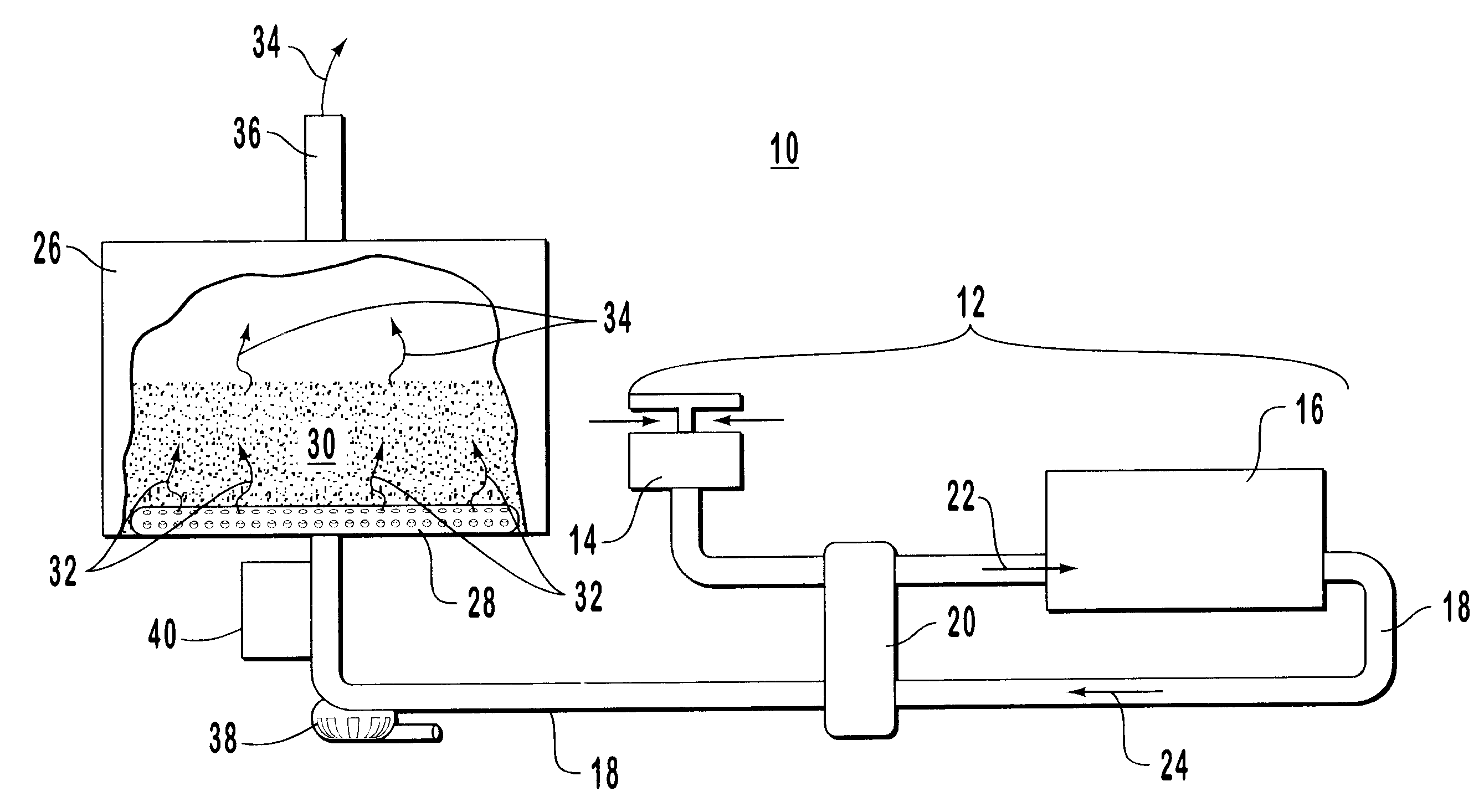
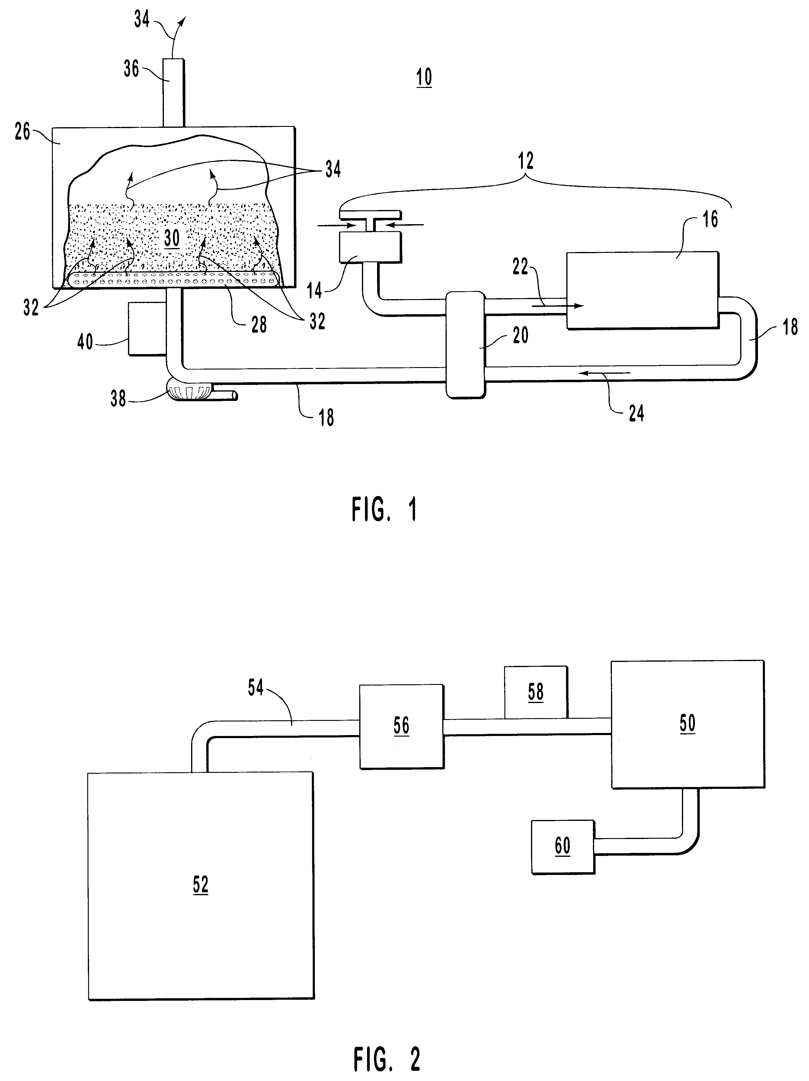
Further experiments were carried out using the apparatus described in Example 1, in which the temperature of the exhaust gases coming out the turbo was measured at 833.degree. F. at a back pressure of 29 inches of water, at full load. This back pressure was caused mostly by the resistance of the diffusion pipe. After passing through the muffling / reaction chamber, the temperature of the waste gases dropped to about 125.degree. F. The waste gases included virtually no measurable soot, hydrocarbons, or CO. The considerable drop in temperature was postulated to be due to the catalytic reactions occurring with the reaction chamber. The sound was greatly muffled and did not exceed 100 db. The inside of the diffusion pipe showed considerable buildup of soot and oily hydrocarbons but was totally clean in the region of the holes adjacent the silica particles.

example 3

Further experiments were carried out using the apparatus described in Example 1, except that the silica sand was not fluidized as much but was kept in only a slightly elevated state. Furthermore, after the diesel engine was warmed up all auxiliary heat was cut off such that the only heat input into the reaction chamber was provided by the diesel engine exhaust. A series of measurements indicated that the temperature leveled off and remained at about 180.degree. C. The treated exhaust gases were sampled and found to be virtually emission free. In particular, the filter paper used to sample particulates from the treated gases remained virtually clean over time (i.e. after sampling for more than 10 minutes), which indicated that over 99% of the particulates were being oxidized without any-additional heat inputs.

Thereafter, large filter paper was placed over the opening of the exhaust stack itself for at least 10 minutes to ensure that the sampling techniques used above were not flawed ...

example 4

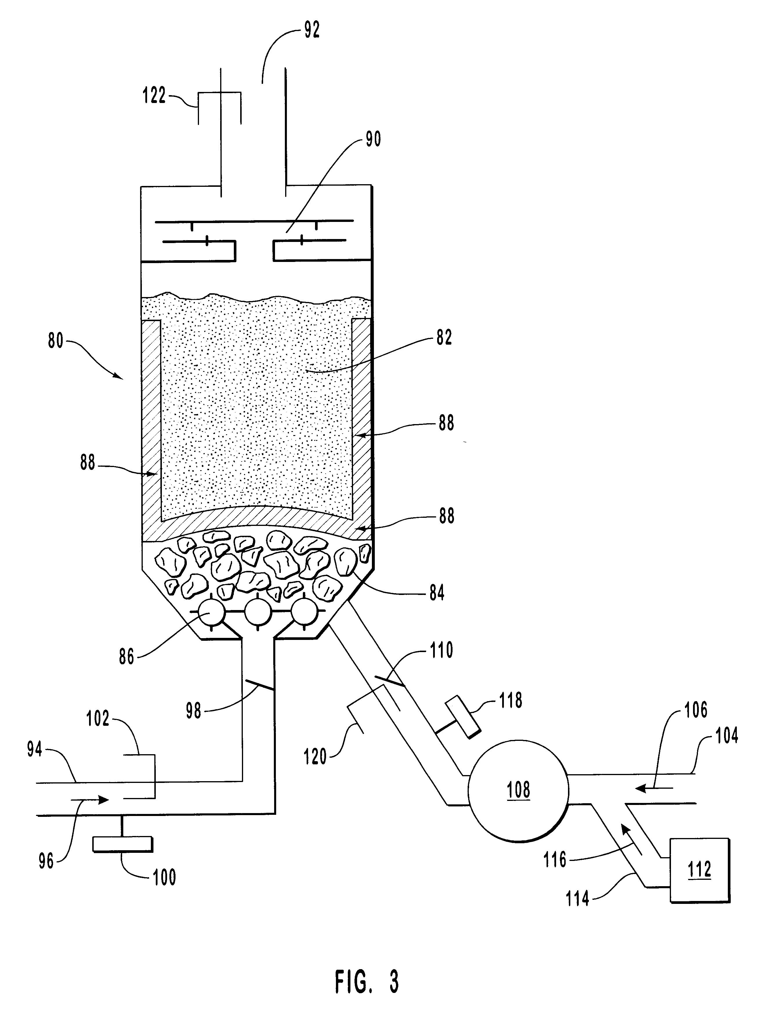
A reaction chamber containing silica is used to remove up to 98% of the soot and other unburnt carbonaceous materials emitted in the flue gas from an industrial burner that utilizes coal or fuel oil. Carbon monoxide and nitrogen oxides are also greatly reduced. Because the industrial plant is stationary, and because silica is extremely inexpensive, an amount of silica appropriate for oxidizing the unburnt components from the industrial burners is used. The temperature is maintained within a range from about 100.degree. C. to about 500.degree. C. by appropriate means, and the moisture content of the gases within the reaction chamber is maintained by appropriate means, such as by, e.g., a humidifier.


PUM


Abstract

Systems and apparatus for muffling sounds produced by an internal combustion engine, and optionally catalytically degrading pollutants within waste exhaust gases. The systems and apparatus utilize a bed of particles within a muffling chamber. The gases are introduced using a diffusion tube with holes therethrough. The muffling particles preferably include silica or alumina, which can also catalytically degrade pollutants. Typically, the muffling / reaction chamber is maintained at a temperature in a range from about 50° C. to about 500° C., which is much lower than temperatures within conventional muffling systems for diesel engines. The muffling systems operate as substantially lower back pressure compared to conventional muffling systems. The systems and apparatus can be adapted to be used in combination with diesel engines or other internal combustion engines and industrial burners.

Description

1. Field of the InventionThe present invention is in the field of muffling apparatus used to reduce the sound emitted by internal combustion engines. More particularly, the present invention involves methods and systems for muffling the sound emitted by internal combustion engines while maintaining low back pressure for improved power and fuel economy. The methods and systems employ a bed of silica, alumina or other appropriate particulate material for absorbing and / or disrupting sound waves.2. Review of the Relevant TechnologyInternal combustion engines are ubiquitous in modern life but have the drawback of producing considerable noise, particularly from the exhaust pipe. To effectively muffle and reduce engine noise to within acceptable levels, exhaust pipes are typically equipped with sophisticated channeling and baffling schemes. Because muffling systems typically involve restricting the free flow of exhaust gasses in order to disrupt or otherwise dampen the sound waves generate...

Claims


Application Information

Patent Timeline
Patent Type & Authority Patents(United States)
IPC IPC(8): F01N3/035F01N3/08F01N1/08F01N7/00F01N7/02F01N13/02
CPCF01N1/081F01N3/035F01N3/0842F01N3/085F01N3/0871F01N3/0885F01N13/009F01N2590/08
Inventor MAGANAS, THOMAS C.HARRINGTON, ALAN L.
Owner THOMAS C MAGANAS & STELLA MAGANAS 1988 FAMILY TRUST
Why Eureka
Try Eureka