Self-regenerative process for contaminant removal from ammonia

a technology of ammonia and contaminant removal, which is applied in the direction of physical/chemical process catalysts, separation processes, other chemical processes, etc., can solve the problems of affecting the performance and operability of the integrated circuit, lattice defects, and similar detrimental effects

Inactive Publication Date: 2003-02-25
ENTEGRIS INC
View PDF9 Cites 35 Cited by
  • Summary
  • Abstract
  • Description
  • Claims
  • Application Information

AI Technical Summary

Problems solved by technology

Such products are extremely sensitive to the presence of electron-donating n-type materials, and very small concentrations of such n-type are sufficient to deactivate the p-type dopants and impair or destroy the performance and operability of the integrated circuits, LEDs and blue lasers.
Oxygen is a particularly efficient n-type material, and the presence of molecular oxygen causes lattice defects and is detrimental to the desired band gap properties in the semiconductor or laser material.
Similar detrimental effects are observed with similar low concentrations of water or hydrocarbons in the manufacturing system.
A common requirement in these processes is that all reactants, catalysts, carriers, etc. must have the least practical contaminant level, since the products produced must be of very high purity.
However, copper tends to migrate over a period of time, so it is necessary to construct barrier layers in the semiconductor to prevent the copper migration.
As mentioned, in addition to oxygen contamination, the presence of water vapor, gaseous hydrocarbons and / or carbon dioxide gas in hydride gases such as ammonia is also detrimental, since those materials lead to degradation of the products formed by deposition of active layers of metals or metal compounds from a hydride gas environment.
Water is one of the most common and yet most difficult impurities to remove from the gases.
In the manufacture of such products, moisture contents of the depositing gases which are in the ppm range are excessively wet.
Attempts to use materials such as reduced nickel or copper catalysts to remove contaminants such as oxygen, carbon dioxide and water from hydride gases have not been successful.
While contaminant removal can be effected for short periods of time down to the 10 ppb level, the reactive effects of the hydride gases, especially ammonia, very quickly cause the materials to degrade and contaminate the gas stream with metal complexes.
Though pre-existing impurities may be reduced, the introduction of new impurities to the manufacturing process is unacceptable.
However, these have been relatively ineffective at reaching sufficiently low levels of decontamination.
Further, the reference processes are usually not effective for removal of carbon dioxide or water, as compared to oxygen, from ammonia gas streams.
Consequently, the problem of removal of contaminant levels down to .ltoreq.100 ppb from ammonia remains a significant problem in the field of production of high purity LEDs, blue lasers, semiconductors, and the like.
Those processes which are being used are expensive because of the very short service life of the decontaminating materials and the need for their frequent replacement.
In addition, since it is difficult to determine the exact rate of deterioration of the decontaminating materials in the presence of the ammonia, users of such decontaminating materials must schedule their discard and replacement at intervals less than the shortest expected service life.
To do otherwise would risk failure of a decontamination unit with the resultant loss of contaminated product when the excessive contaminant concentrations reaches the production chamber through the failed unit.
Consequently, the current systems require that many if not most of the decontamination units must be discarded while they still have some degree of useful service life left, thus further increasing the expense of the system operations.
Therefore the more that a process deviates from these anticipated parameters, the less acceptable it is.
While ammonia decontamination systems have been described that include multiple adsorbent beds or vessels that alternate in decontaminating and regenerative function, such systems suffer drawbacks in that they either a) require the periodic replacement of adsorbent, e.g., a getter alloy, and / or b) involve a regenerative process that relies on the administration of gas from outside the system to generate fresh adsorbent, e.g., alumina, from contaminant-saturated adsorbent.
This required more handling and plumbing, which in turn exacted a toll on overall process efficiency.
The dilution must not, however, be so great that the volume of hydrogen resulting from the cracking is insufficient for regenerate of the second bed.
It will be recognized that the limitation on degree of any such dilution will be related to the degree of cracking that occurs in the cracking reactor.

Method used


Image

  • Self-regenerative process for contaminant removal from ammonia
  • Self-regenerative process for contaminant removal from ammonia
  • Self-regenerative process for contaminant removal from ammonia

Examples


Embodiment Construction

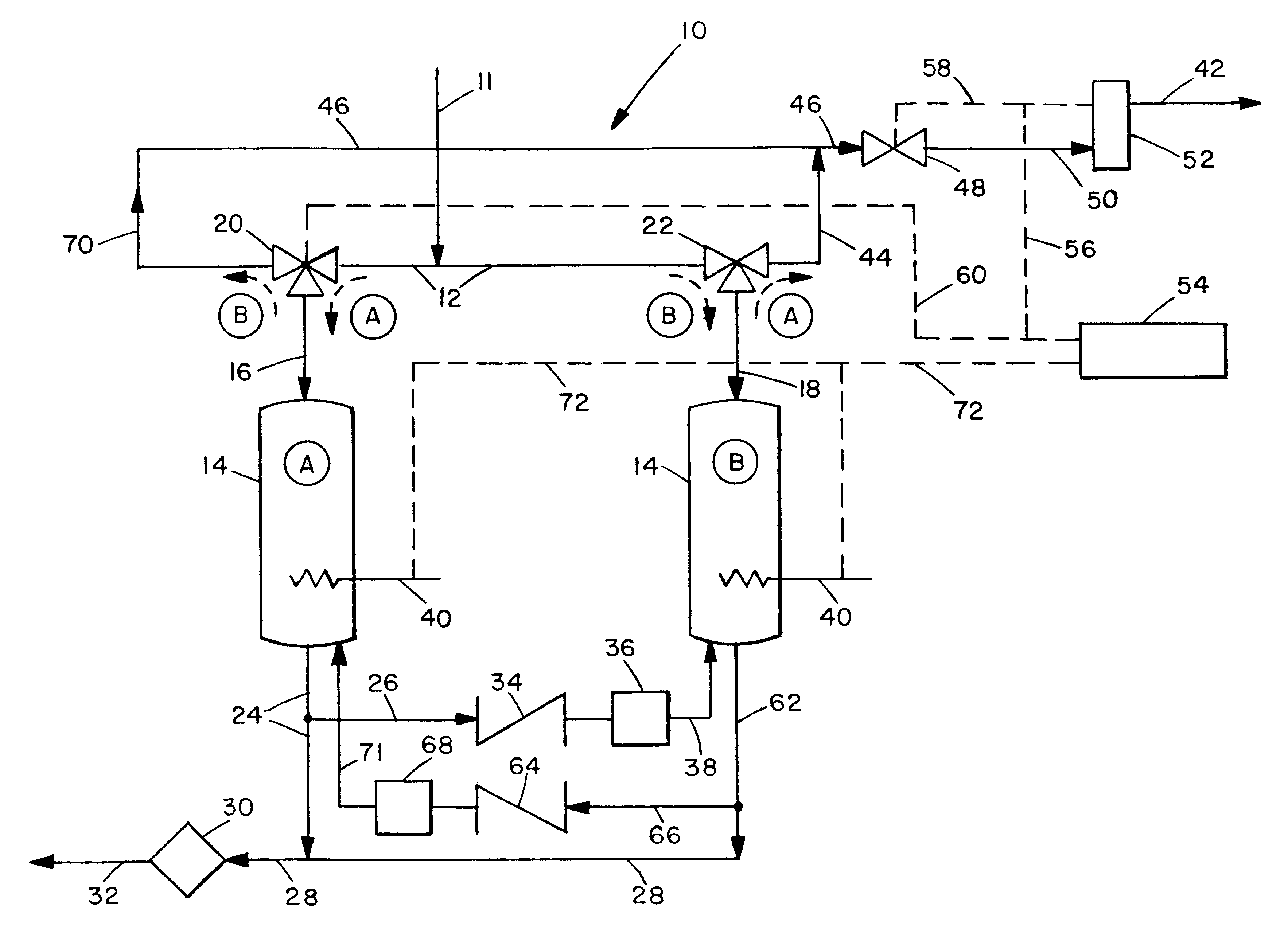
The invention is based on the continuous, self-contained purification of ammonia made possible by an integrated means for decomposing a fraction of the ammonia into its constituent gases hydrogen and nitrogen, with the hydrogen in turn being used to reduce and thereby regenerate adsorbent beds when needed. This allows, in preferred embodiments, for the alternating and continued use of ammonia decontamination vessels.

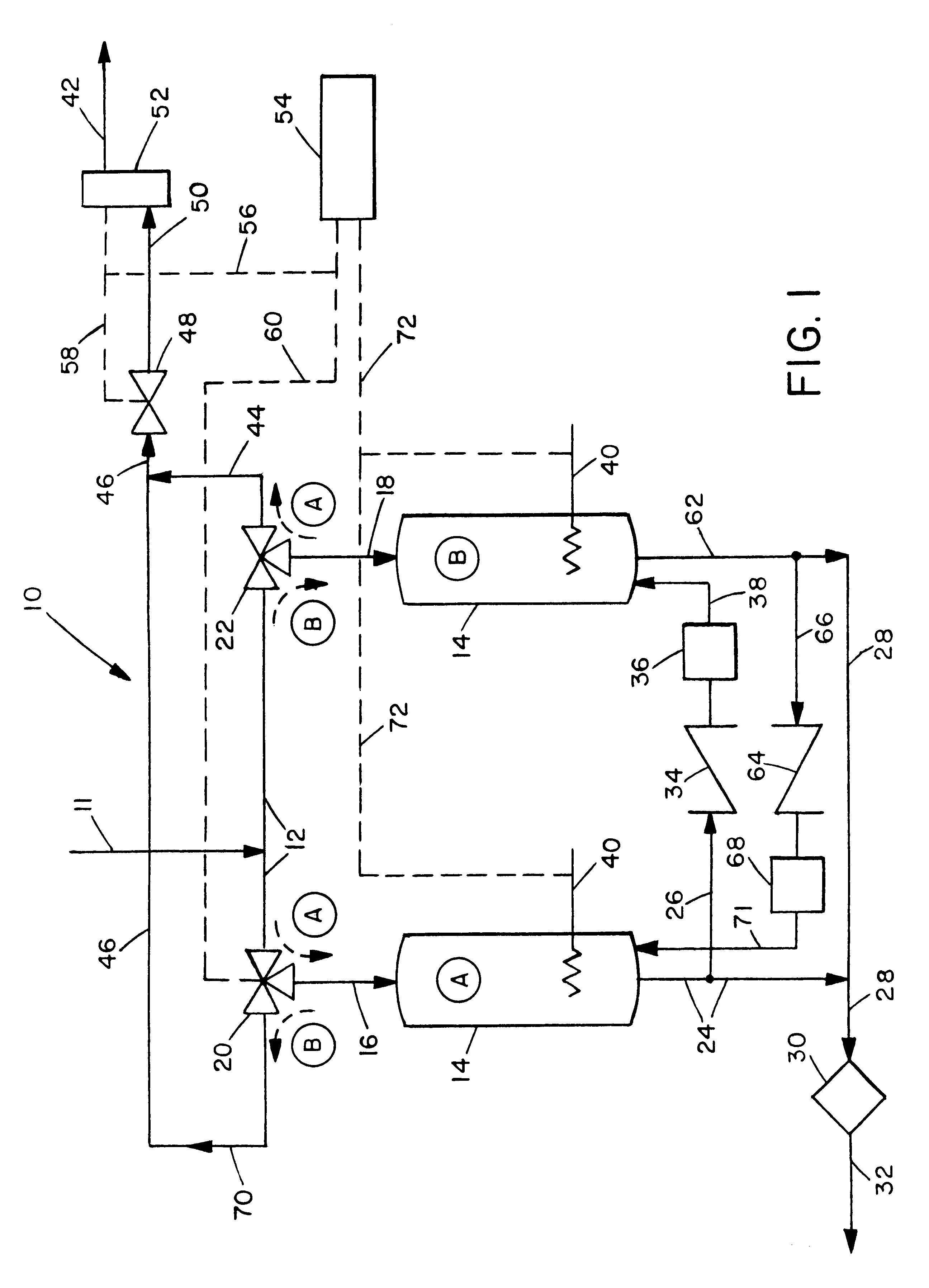
The invention is best understood by reference to FIG. 1. Contaminated ammonia is passed to the decontamination system 10 through line 11. It then passes into line 12 through which it can alternatively be passed to either of the vessels 14 (identified separately as A and B). For the following description it will be assumed that initially vessel A is the decontamination site and vessel B is the vessel which is undergoing regeneration. In this operating mode the contaminated fluid ammonia is passed through line 12 to three-way valve 20 through which it is diverted to line 1...


PUM

PropertyMeasurementUnit
temperatureaaaaaaaaaa
temperaturesaaaaaaaaaa

Abstract

A method and apparatus for the decontamination of fluid ammonia are described. Liquid or gaseous ammonia is purified of contaminants by passage through an adsorbent bed, the contaminants accumulating in the bed. A portion of the purified ammonia discharged from the bed is decomposed to hydrogen and nitrogen. The hydrogen is used to regenerate an adsorbent bed which has accumulated sufficient contaminants to reduce its ability to further decontaminate incoming ammonia satisfactorily. Preferably there are a plurality of interconnected adsorbent beds, with some being operated for ammonia decontamination while others are being regenerated, with their operations being reversed as needed to maintain a continual production of decontaminated ammonia from the plurality of beds. Computers or other controllers can be used to control such bed operations and interchanges. Internal production of hydrogen makes the system self-contained and no addition of hydrogen is needed.

Description

1. Field of the InventionThe invention relates to the removal of contaminants from streams of ammonia gas and liquid. More particularly it relates to the production of substantially contaminant-free streams of ammonia gas or liquid for use in the production of semiconductors and similar products which cannot tolerate the presence of such contaminants during manufacture.2. Background ArtThere is current research to develop high performance light emitting diodes (LEDs). Such LEDs are intended for such disparate uses as in outdoor displays, vehicles, traffic signals, lasers, medical devices and indoor lighting, and are expected to replace the current bulbs or fluorescent lighting tubes. The high performance LEDs emit light of specific wavelengths compared to broad spectrum wavelength emissions of prior bulbs and tubes, so that optimal light spectra can be provided for each end use by combination of LEDs of different colors. For instance, LED combinations with spectra matching incandesc...

Claims


Application Information

Patent Timeline
Patent Type & Authority Patents(United States)
IPC IPC(8): B01J20/30B01J20/34B01D15/00H01S3/00
CPCB01D15/00B01J20/3458H01S3/005C01C1/024B01J20/28057B01J20/3433B01J20/3483B01J20/06B01J2220/56
Inventor ALVAREZ, JR., DANIELSPIEGELMAN, JEFFREY J.
Owner ENTEGRIS INC
Why Eureka
Try Eureka