Conductive roller, process cartridge and image forming apparatus

a technology of image forming apparatus and conductive roller, which is applied in the direction of corona discharge, plastic/resin/waxes insulators, instruments, etc., can solve the problems of large fluctuation of resistivity, affecting the charging performance, and affecting the charging uniformity of the charging member,

Inactive Publication Date: 2003-05-06
CANON KK
View PDF15 Cites 38 Cited by
  • Summary
  • Abstract
  • Description
  • Claims
  • Application Information

AI Technical Summary

Problems solved by technology

However, charging performance, inclusive of charging uniformity of the charging member, is liable to be affected by good or poor dispersion of the electroconductive particles in the electroconductive elastic layer in not a few cases.
For example, poor dispersion of electroconductive carbon black in the rubber has resulted in resistance irregularity of the charging member, leading to the occurrence of density irregularity or black spots corresponding to rotation periods of the charging member in halftone images or solid white images.
However, though the use of such a known ionic conductive agent provides an improved dispersibility of the conductive agent, a larger fluctuation of resistivity is liable to be caused by a change of environmental condition.
Moreover, in the case of using such a known ionic conductive agent, the ionic conductive agent is liable to bleed out of the electroconductive elastic layer with time, thus changing the resistivity of the charging member.
Further, the ionic conductive agent having bled out of the electroconductive elastic layer migrates to the surface of the resistance layer, thereby causing cracks in the surface of the electroconductive photosensitive member contacting the charging member and sticking with the photosensitive member.
Further, because of the ionic conductive agent having migrated to the surface of the resistance layer, the developer is liable to be attached to the charging member surface, thus causing a periodical density irregularity in the resultant images corresponding to the rotation period of the charging member.
Further, in the case of using a charging member including an electroconductive elastic layer containing an alkaline metal perchlorate as an ionic conductive agent according to the DC charging scheme for image formation, halftone images formed in a low temperature / low humidity environment are liable to be accompanied with minute black spots, black streaks or lateral white streaks.
However, as the conductive roller of the present invention has a very excellent uniform conductivity, it is particularly suitably used in the DC charging scheme wherein the charging performance is liable to be non-uniform.
% or below is liable to cause bleeding out of the above-mentioned additives because of relatively poor mutual solubility.
ve. Below 10 wt. parts of the ammonium perchlorate compound, it is difficult to impart an appropriate level of electroconducti
nd. Below 1 wt. part, the effect is liable to be insufficient, and above 100 wt. parts, the resultant roller surface is liable to be
cted. An addition amount in excess of 20 wt. parts does not result in a further lowering in resistivity but rather results in a lower mechanical strength of the resultant electroconductive elastic
If the volume resistivity exceeds 1.times.10.sup.10 ohm.cm, a substantial decrease in applied voltage is liable to occur in the electroconductive elastic layer, thus failing to supply a sufficient charge current and to satisfactorily charge the electrophotographic photosensitive member.
If the elongation exceeds 700%, the surface polishability becomes worse and it becomes difficult to provide a desirable surface roughness Rz (ten-point average roughness according to JIS-B0601) of at most 10 .mu.m.
If the hardness exceeds 60 degrees, the conductive roller is liable to cause a contact irregularity along a longitudinal direction thereof at a contact portion with the photosensitive member.
If the volume resistivity is below 1.times.10.sup.7 ohm.cm, in the case where surface defects, such as pinholes and scars, are present on the photosensitive drum, the difficulty of "charge leakage" that charges cannot be retained over a substantial contact region is liable to occur.
When such "charge leakage" occurs, the resultant image is accompanied with a white dropout region in the case of a normal development scheme or a black dropout region in the case of a reversal development scheme, which causes a substantial lowering of image quality.
If the volume resistivity exceeds 1.times.10.sup.12 ohm.cm, a substantial lowering of applied voltage is liable to occur, thus failing to provide an appropriate level of charge current and to provide a sufficient charge to the photosensitive member.
Moreover, minute lateral black streaks are liable to be caused.
If the ratio is below 1, i.e., the resistance layer has a lower resistivity than the elastic layer, charge leakage to defects of the photosensitive member is liable to occur, and above 10.sup.4 times, the charging performance is liable to be non-uniform.
If the thickness exceeds 1000 .mu.m, the vaporization of the solvent takes a substantial time, thus being liable to lower the productivity.

Method used


Image

  • Conductive roller, process cartridge and image forming apparatus
  • Conductive roller, process cartridge and image forming apparatus
  • Conductive roller, process cartridge and image forming apparatus

Examples


example 1

The following ingredients were uniformly mixed in solution to prepare Additive 1.
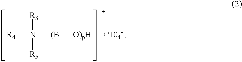
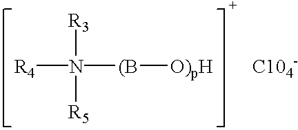
Additive 1

(Preparation of Electroconductive Elastic Layer of Charging Members)

Several coating compositions were each prepared by kneading the following ingredients for 15 min. in a pressure kneader temperature-controlled at 20.degree. C.

To the above-kneaded product, 2 wt. parts of benzothiazyl disulfide (vulcanization promoter) and 0.5 wt. part of tetrathiuram monosulfide (vulcanization promoter) were added, and the resultant mixture was kneaded for 5 min. on a two-roll mill temperature-controlled at 50.degree. C., to prepare an electroconductive compound.

Separately, a stainless steel bar of 6 mm in outer diameter and 258 mm in length was provided as a conductive support (core metal), and the outer surface thereof was coated with a layer of the above-prepared electroconductive compound formed by extrusion, followed by vulcanization under heating at 170.degree. C. for 15 min. The coating layer was furthe...

example 2

(Preparation of Electroconductive Elastic Layers)

Each composition represented above (having a variable amount of Additive 1) was kneaded for 10 minutes in a pressure kneader temperature-controlled at 20.degree. C. To the kneaded product, 1 wt. part of sulfur and 2 wt. parts of ethylenethiourea (vulcanization promoter) were added, and the resultant mixture was kneaded for 5 minutes on a two-roll mill temperature controlled at 50.degree. C., to prepare an electroconductive compound.

By using the electroconductive compounds, 8 types of elastic rollers each having an electroconductive elastic layer as the surfacemost layer were prepared otherwise in the same manner as in Example 1.

The properties (Rv (ohm.cm), Eb (%), Rz (.mu.m) and IRHD (deg.)) of the thus formed 8 electro-conductive elastic layers (Examples 2-1 to 2-8) of the elastic rollers were measured in the same manner and are listed in the following Table 3.

(Resistance Layer for Example 2)

A resistance layer paint was prepared from...

example 3

(Preparation of Electroconductive Elastic Layers)

Each composition represented above (having a variable amount of Additive 1) was kneaded for 10 minutes in a pressure kneader temperature-controlled at 20.degree. C. To the kneaded product, 1 wt. part of sulfur and 2 wt. parts of ethylenethiourea (vulcanization promoter) were added, and the resultant mixture was kneaded for 5 minutes on a two-roll mill temperature-controlled at 50.degree. C., to prepare an electroconductive compound.

By using the electroconductive compounds, 8 types of elastic rollers each having an electroconductive elastic layer as the surfacemost layer were prepared otherwise in the same manner as in Example 1.

The properties (Rv (ohm.cm), Eb (%), Rz (.mu.m) and IRHD (deg.)) of the thus formed 8 electro-conductive elastic layers (Examples 3-1 to 3-8) of the elastic rollers were measured in the same manner and are listed in the following Table 5.

(Resistance Layer for Example 3)

A resistance layer paint was prepared from...


PUM

PropertyMeasurementUnit
thicknessaaaaaaaaaa
thicknessaaaaaaaaaa
surface roughnessaaaaaaaaaa

Abstract

An electroconductive roller is capable of exhibiting stable conductivity regardless of environmental change and is accompanied by small bleed-out of additives. The conductive roller includes an electroconductive support, an electroconductive elastic layer coating the support and a resistance layer coating the elastic layer; wherein the elastic layer comprises at least one species of rubber selected from the group consisting of acrylonitrile-butadiene rubber, epichlorohydrin rubber and chloroprene rubber, an ether oxygen containing alkyl phthalate derivative, a quaternary ammonium perchlorate compound and a fatty oil, and the ether oxygen-containing alkyl phthalate derivative, quaternary ammonium perchlorate compound and fatty oil are contained in a total amount of 0.1-20 wt. parts per 100 wt. parts of the rubber. The conductive roller is suitably used as a contact charging member in an electrophotographic apparatus.

Description

FIELD OF THE INVENTION AND RELATED ARTThe present invention relates to an (electro-)conductive roller, and a process cartridge and an image forming apparatus including the conductive roller. More specifically, the present invention relates to a conductive roller used as a charging member for charging a surface of an electrophotographic photosensitive member as a member to be charged to a prescribed potential by the application of voltage, and a process cartridge and an image forming apparatus including such a conductive roller.As a contact charging member for charging an electrophotographic photosensitive member in an image forming apparatus, there has been conventionally used a charging roller comprising an electroconductive support (core metal) coated successively with an electroconductive elastic layer and a resistance layer. As for the charging scheme, an AC+DC-charging scheme of applying a superposition of AC voltage and DC voltage to the core metal has been principally adopted...

Claims


Application Information

Patent Timeline
Patent Type & Authority Patents(United States)
IPC IPC(8): G03G15/02G03G15/00
CPCG03G15/0233Y10T428/24942Y10T428/28G03G2221/183G03G15/00
Inventor FUEI, NAOKIISHIHARA, YUZIINOUE, HIROSHI
Owner CANON KK
Why Eureka
Try Eureka