
Current collector for SOFC fuel cells

a collector and fuel cell technology, applied in the field of current collectors, can solve the problems of unattractive overall fuel cell system, inability to completely avoid superficial oxide growth, and inability to predict the measures aimed at further matching properties, etc., and achieve the effect of high resistance to corrosion

Inactive Publication Date: 2004-05-18
PLANSEE SE
View PDF6 Cites 33 Cited by
  • Summary
  • Abstract
  • Description
  • Claims
  • Application Information

AI Technical Summary

Benefits of technology

The ferritic iron material according to the invention easily satisfies all the property requirements which have been mentioned above for SOFC high-temperature fuel cells.
The solid electrolyte film with a low thickness is no longer unsupported, but rather the solid electrolyte is applied as a supported film directly to an electrode surface as support material, for example as ASE (anode supported electrolyte) composite component. The thinner a film, the more elastic it becomes. In this way, different coefficients of thermal expansion between the cell components which rest against one another with surface-to-surface contact are compensated for--to a limited extent--without there being a risk of the film tearing.
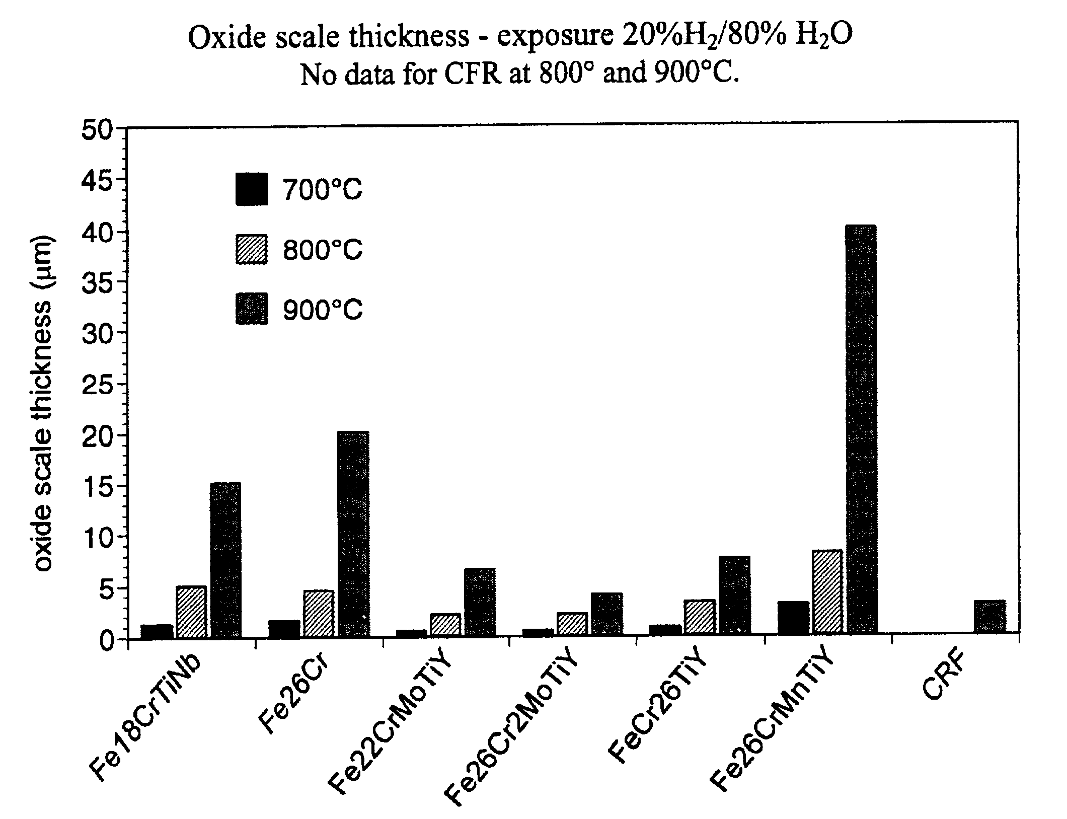
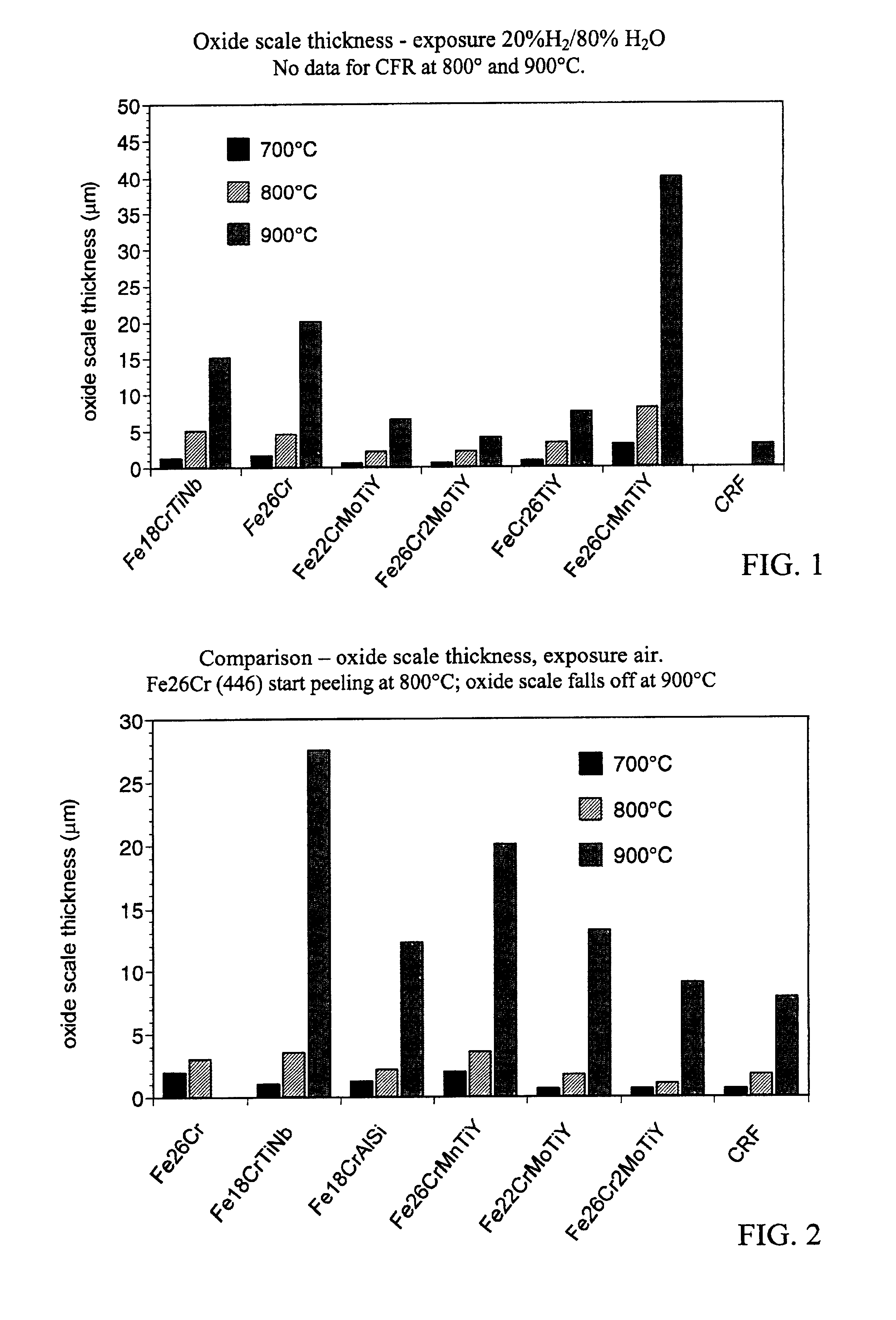
In addition to the good matching of the coefficients of thermal expansion, which is indispensable for current collector materials, the most significant advantage of the ferritic iron material according to the invention compared to the prior art is a surprising and unforeseeable high resistance to corrosion with respect to fuel and exhaust gas atmospheres in the temperature range from 700.degree. C. to 900.degree. C., with the simultaneous formation of advantageous oxidation products in the surface region of the ferritic material.

Problems solved by technology

The material costs alone must not make the overall fuel cells system commercially unattractive.
Even with the ferritic materials, which are known to be resistant to corrosion, it has been impossible to completely avoid superficial growth of oxide.
Known ferritic iron-based materials with a multiplicity of additions which have by now been described, in view of the state which has been reached in the demands for matching a wide range of extremely divergent materials properties, make a prediction about measures aimed at further matching of properties impossible or at least rather dubious.
The validated prior art forms an important platform but not a reliable indicator toward materials developments of this nature.
Alloys containing more than 18% by weight of chromium are considered to be difficult to process.
Despite tests using the Cr and W contents over the entire range covered by the scope of protection of the alloy, it was impossible for the coefficient of thermal expansion of the alloy to be satisfactorily matched to the coefficient for yttrium-stabilized ZrO.sub.2 solid electrolytes.
The resistance to oxidiation, in particular under the hot H.sub.2 / H.sub.2 O vapor atmosphere which is present on the anode side when the cell is operating was recorded to be unsatisfactory.

Method used


Image

  • Current collector for SOFC fuel cells
  • Current collector for SOFC fuel cells

Examples


example 1

The material according to the invention, having the composition Fe, 22% by weight of chromium, 2% by weight of Mo, 0.29% by weight of Ti, 0.37% by weight of Y is processed by powder metallurgy to form the current collector component.

For this purpose, powders of an Fe--Y prealloy are mixed with the metal powders of the other alloying constituents. The alloying powders have a grain size fraction in the range from 30 to 160 .mu.m and are mixed with pressing auxiliaries during the mixing. The powder mixture obtained in this way is pressed in press molds at a pressure of 8 t / cm.sup.2 to form a near net shape current collector plate. Accordingly, all the passage systems for the gaseous media which run on the surface of the plate have already been formed in the compact. The further processing of the compacts to form finished current collector plates takes place by means of sintering at temperatures of 1400.degree. C. in a hydrogen atmosphere. If necessary, the current collector plates obta...

example 2

An alloy of the composition Fe, 26% by weight of Cr, 2% by weight of Mo, 0.25% by weight of Y, contains as impurities 0.08% by weight of Mn, 0.05% by weight of Nb. This alloy is pressed by powder metallurgy to form a cylindrical compact and the compact is then processed into a sintered blank by sintering in an H.sub.2 atmosphere at 1400.degree. C. The sintered blank is cut into disks, and the surface gas-guiding passages are produced by means of mechanical or electrochemical processes. Two current collectors which have been manufactured in this way, as cover plates, are combined with the thin films comprising anode and cathode material and with a gadolinium oxide-stabilized cerium oxide SOFC electrolyte to form a cell unit and are tested at a cell temperature of 800.degree. C. under the standard fuel gas and exhaust gas atmospheres for an operating time of 650 hours. In addition to the mechanical stability of the individual cell components, in particular the corrosion properties of ...


PUM

PropertyMeasurementUnit
temperaturesaaaaaaaaaa
electrical voltagesaaaaaaaaaa

Abstract

The ferritic iron alloy is particularly suitable as a material for current collectors used in SOFC solid electrolyte high-temperature fuel cells. The material has a high chromium content upwards of 22% by weight, and a molybdenum content of 1 to 10% by weight. Additionally, there is provided 0.01 to 1.5% by weight of yttrium, rare earth metals, and / or their oxides. The alloy in particular has a high resistance to corrosion under the standard cell atmospheres in the temperature range from 700.degree. to 900.degree. C.

Description

BACKGROUND OF THE INVENTIONField of the InventionThe invention pertains to a current collector made from ferritic iron alloy for electrically connecting and mechanically supporting a set of individual, planar SOFC high-temperature fuel cells (solid oxide fuel cells). The fuel cells comprise an anode, an electrolyte, and a cathode, operate at temperatures of between 700.degree. C. and 900.degree. C., and are equipped with a solid electrolyte.In recent years, SOFC high-temperature fuel cells have experienced considerable progress in development and are beginning to become economically viable. The SOFC-type fuel cell is wherein by a plate-like structure and a solid oxide ceramic electrolyte. Different oxide ceramic electrolytes, for example doped zirconium oxide (zirconia) or cerium oxide (ceria), are used depending on the working temperature selected for the cell in the range between 500.degree. and 1000.degree. C. The cell voltage of an individual fuel cell is approximately 1 volt, a...

Claims


Application Information

Patent Timeline
Patent Type & Authority Patents(United States)
IPC IPC(8): C22C33/02C22C38/00C22C38/28C22C38/22H01M8/02H01M8/12H01M8/0232H01M8/0247H01M8/124H01M8/1253H01M8/126
CPCC22C33/0228C22C33/0285C22C38/005C22C38/22C22C38/28H01M8/0232H01M8/0247H01M8/1253H01M8/126H01M2008/1293Y02E60/50Y02E60/525H01M8/021H01M8/0219H01M8/0228H01M8/0236H01M8/0245H01M4/88H01M8/10Y02P70/50
Inventor JANOUSEK, MARTINGLATZ, WOLFGANGHONEGGER, KASPAR
Owner PLANSEE SE
Learn More