Multiple-source arrays with optical transmission enhanced by resonant cavities
a multi-source array and resonant cavity technology, applied in the direction of instruments, material analysis through optical means, optical elements, etc., can solve the problems of low optical efficiency, sub-wavelength probes used as near-field scanning probes can have a negative impact on signal-to-noise ratio and measurement bandwidth
- Summary
- Abstract
- Description
- Claims
- Application Information
AI Technical Summary
Benefits of technology
Problems solved by technology
Method used
Image
Examples
first embodiment
For certain of the embodiments disclosed herein, light sources corresponding light source 10 may also be a pulsed source. There are several different procedures for producing a pulsed source [see Chapter 11 entitled “Lasers”, Handbook of Optics, 1, 1995 (McGraw-Hill, New York) by W. Silfvast]. There may be a restriction on the pulse width. For example, the pulse width may be based on a consideration of the spatial resolution required for a scanning end-use application and / or enhancement properties of the first embodiment as subsequently described.
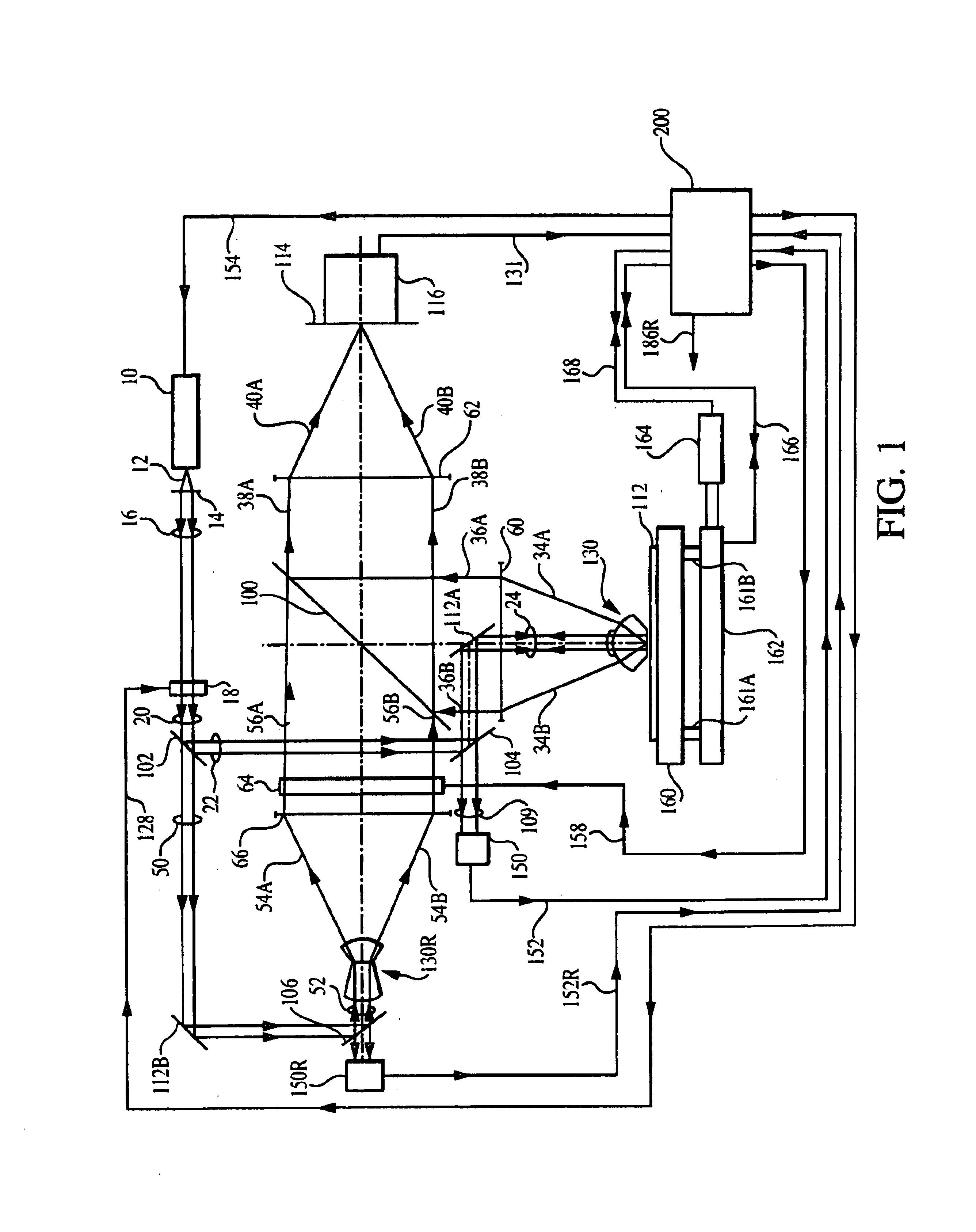
For the first embodiment, light source 10 is preferably a monochromatic point source or a spatially incoherent source of radiation across surface of the source, preferably a laser or like source of coherent or partially coherent radiation, and preferably polarized. Light source 10 emits input beam 12. As shown in FIG. 1, input beam 12 enters collimating lens 14 to form input beam 16. Input beam 16 is transmitted by a phase retardation plate...
second embodiment
The condition Φ2=0 will be met only to a certain accuracy by the servo control of the wavelength of beam 16 or the optical path length of optical cavity 130. The effects of the certain accuracy in down stream applications may be compensated in the second embodiment using measured values of phase shift Φ2.
The description of the generation of the servo control signal 186R for the reference optical cavity of the second embodiment is the same as corresponding portions of the description given for the generation of servo control signal 186 of the second embodiment.
The remaining description of the second embodiment is the same as corresponding portions of the description given for the first embodiment and variant thereof of the present invention.
Advantages of the second embodiment are the generation by interferometric techniques the servo control signals for the optical cavities of the second embodiment leading to increased signal-to-noise ratios, direct measurements of a relative phases ...
third embodiment
Phase shifter 64 may be used in the third embodiment to confirm that the values of phase shifts produced by the combination of the timing of the pulses from source 1010 and modulator 76 are equivalent to a desired set of phase shifts.
It will be evident to those skilled in the art that source 1010 of the third variant of the first embodiment may be replaced with a CW source and the phases of arrays of signal values [Sn] determined using known heterodyne detection techniques or phase sensitive detection techniques for non-pulsed signals such as a digital Hilbert transform phase detector [see “Phase-locked loops: theory, design, and applications” 2nd ed. (McGraw-Hill, New York) 1993, by R. E. Best], a phase-locked loop [see R. E. Best, ibid.], a sliding window FFT [see Digital Techniques for Wideband Receivers, (Artech House, Boston) 1995, by J. Tsui], without departing from either the scope or spirit of the present invention.
It will also be evident to those skilled in the art that the...
PUM
 Abstract
Description
Claims
Application Information
 - R&D
- Intellectual Property
- Life Sciences
- Materials
- Tech Scout
- Unparalleled Data Quality
- Higher Quality Content
- 60% Fewer Hallucinations
Browse by: Latest US Patents, China's latest patents, Technical Efficacy Thesaurus, Application Domain, Technology Topic, Popular Technical Reports.
© 2025 PatSnap. All rights reserved.Legal|Privacy policy|Modern Slavery Act Transparency Statement|Sitemap|About US| Contact US: help@patsnap.com


