

Method and apparatus for performing pattern defect repair using Q-switched mode-locked pulse laser
a laser and mode-locked pulse technology, applied in the direction of manufacturing tools, semiconductor/solid-state device details, instruments, etc., can solve the problems of pattern defect, reduced fabrication accuracy, and heat affected zone having a length of about 0.5 m to 1.0 m, so as to prevent the occurrence of the heat affected zone that was produced during laser irradiation time, the effect of negligible heat affected zone and greatly improved fabrication accuracy
- Summary
- Abstract
- Description
- Claims
- Application Information
AI Technical Summary
Benefits of technology
Problems solved by technology
Method used
Image

Examples
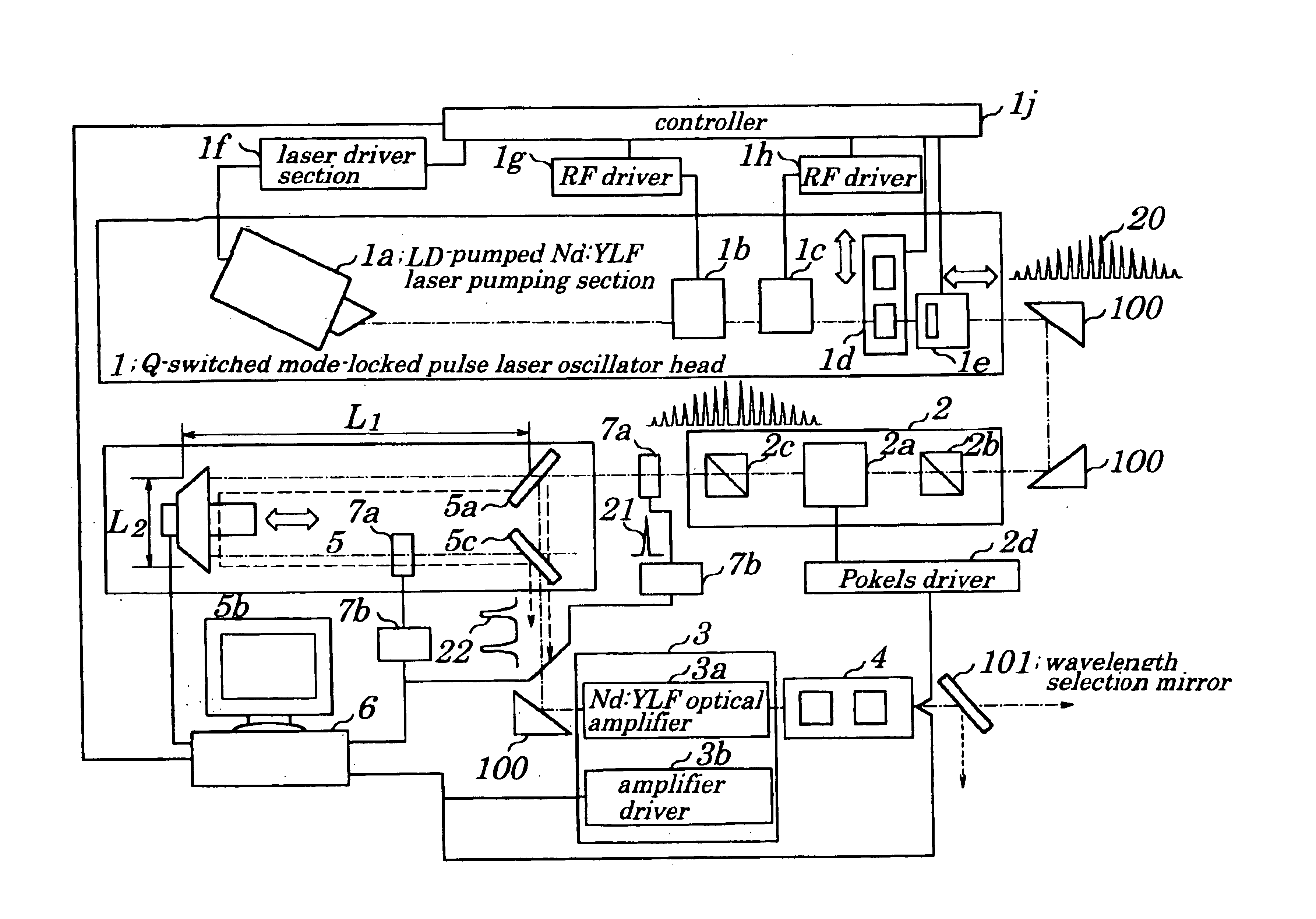
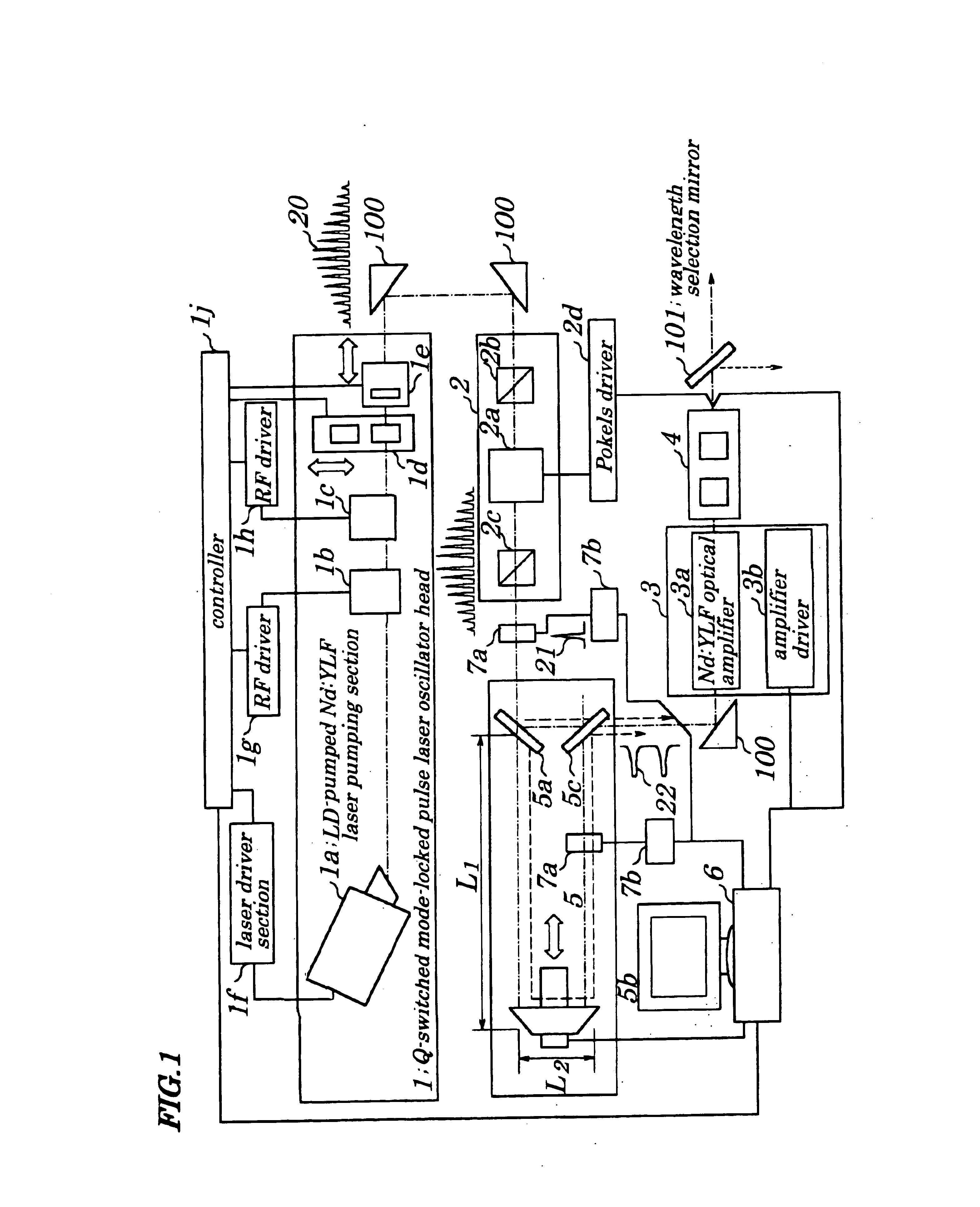
first embodiment
First, in zapping processing, to reduce a heat affected zone to a minimum is most important. A length of thermal diffusion Ld is given by:
Ld=(κ·t)1 / 2
where “κ” denotes a thermal diffusion coefficient and “t” denotes a laser pulse width. The “κ” is a value being peculiar to metal. Therefore, to decrease the length of thermal diffusion, there is no other choice but to decrease the laser pulse width. The metal on a mask on which patterning is performed is ordinarily Cr (Chromium). Since the value “κ” of Cr is 1.96×10⁻⁵ [m2 / s], the thermal diffusion length is 0.14 μm when the pulse width of the laser is 1 ns.
When the zapping is performed on the photomask pattern with minimum line width of not more than 0.18 μm and use of a one-fourth reduction exposure method is considered, since an actual size of the pattern on the photomask is 0.72 μm (fourfold), allowable fabrication accuracy is at most 10% of a line and space (L / S) of the patterns, that is, 0.072 μm. In otherwords, even if the minimu...
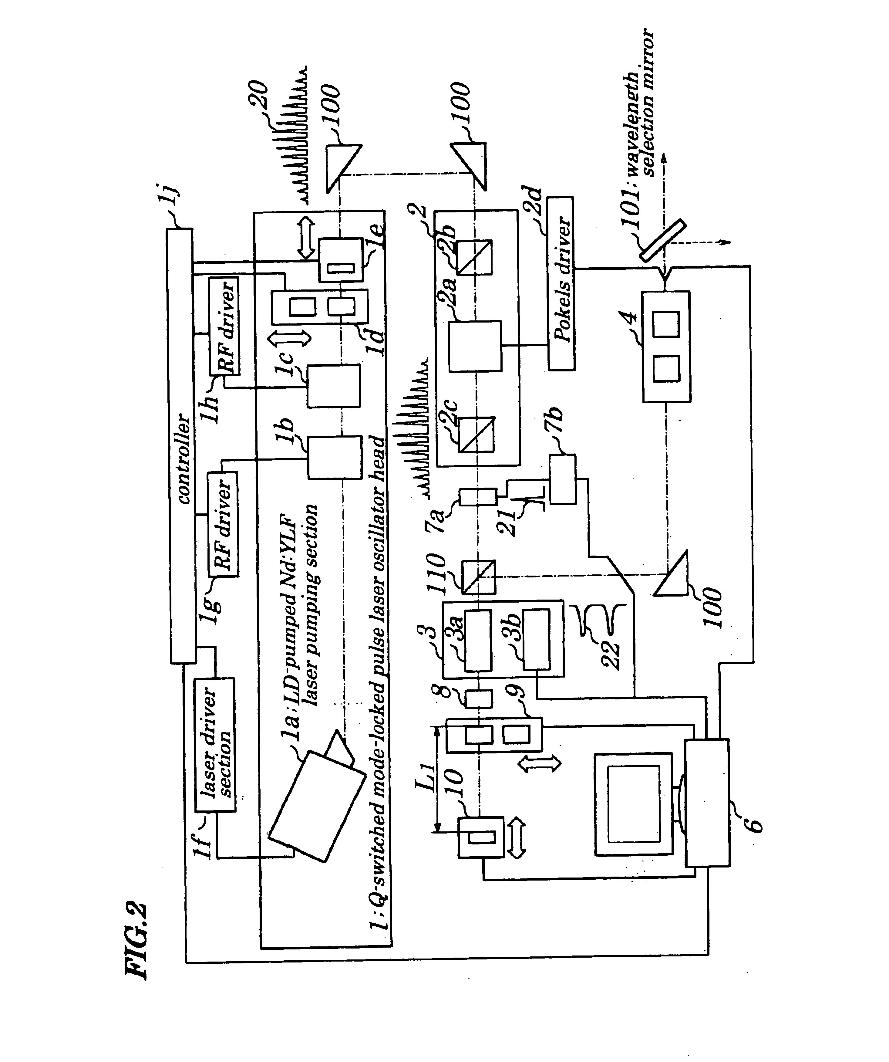
second embodiment
FIG. 2 is a schematic block diagram showing configurations of a laser-based repair apparatus according to a second embodiment of the present invention. Configurations of the laser repair apparatus of the second embodiment differ from those in the first embodiment in that an optical amplifier is of a double-pass type amplifier adapted to cause light to pass through the optical amplifier in a reciprocating manner. In the first embodiment, the optical amplifier is of a one-pass type amplifier. Therefore, in the second embodiment, a polarization beam splitter 110 is provided in front of an optical amplifier 3 and a ¼ wavelength plate 8; a partial transmissive mirror 9 and a total reflection mirror with a moving mechanism 10 used to delay laser light transmitted through the partial transmissive mirror 9 by a distance 2L1 are provided behind the optical amplifier 3. The partial transmissive mirror 9 is so configured that partial transmissive mirrors 9 each having different reflectance (tr...
PUM
| Property | Measurement | Unit |
|---|---|---|
| time delay | aaaaa | aaaaa |
| time delay | aaaaa | aaaaa |
| delay time | aaaaa | aaaaa |
Abstract
Description
Claims
Application Information