

PVD-coated cutting tool insert
a cutting tool and pvd coating technology, applied in the field of pvd-coated cutting tool inserts, can solve the problems of increasing the heat generation in the cutting zone, affecting the cutting speed, etc., to achieve excellent performance, high cutting speed, and enhanced cutting performance
- Summary
- Abstract
- Description
- Claims
- Application Information
AI Technical Summary
Benefits of technology
Problems solved by technology
Method used
Image

Examples
example 1
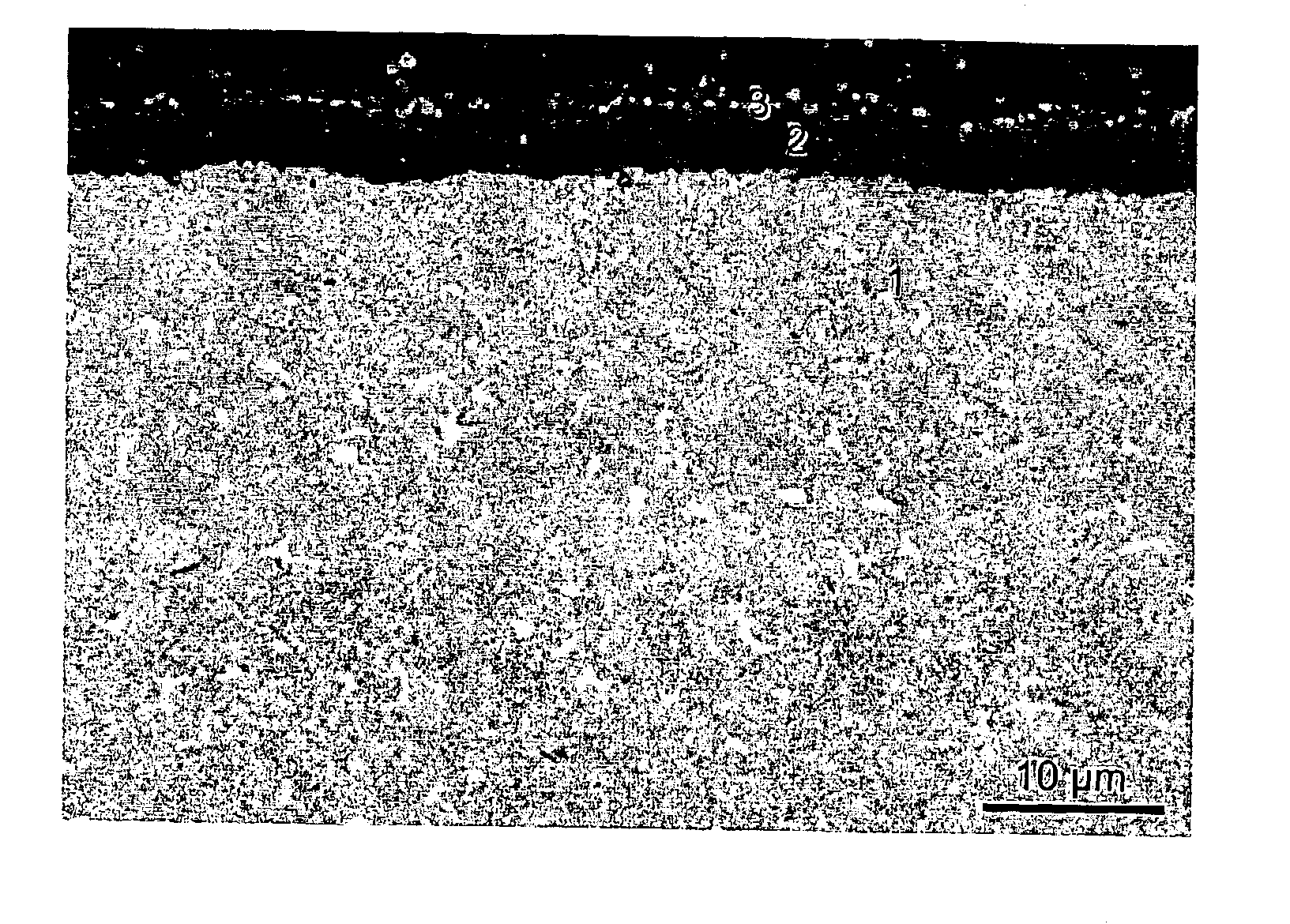
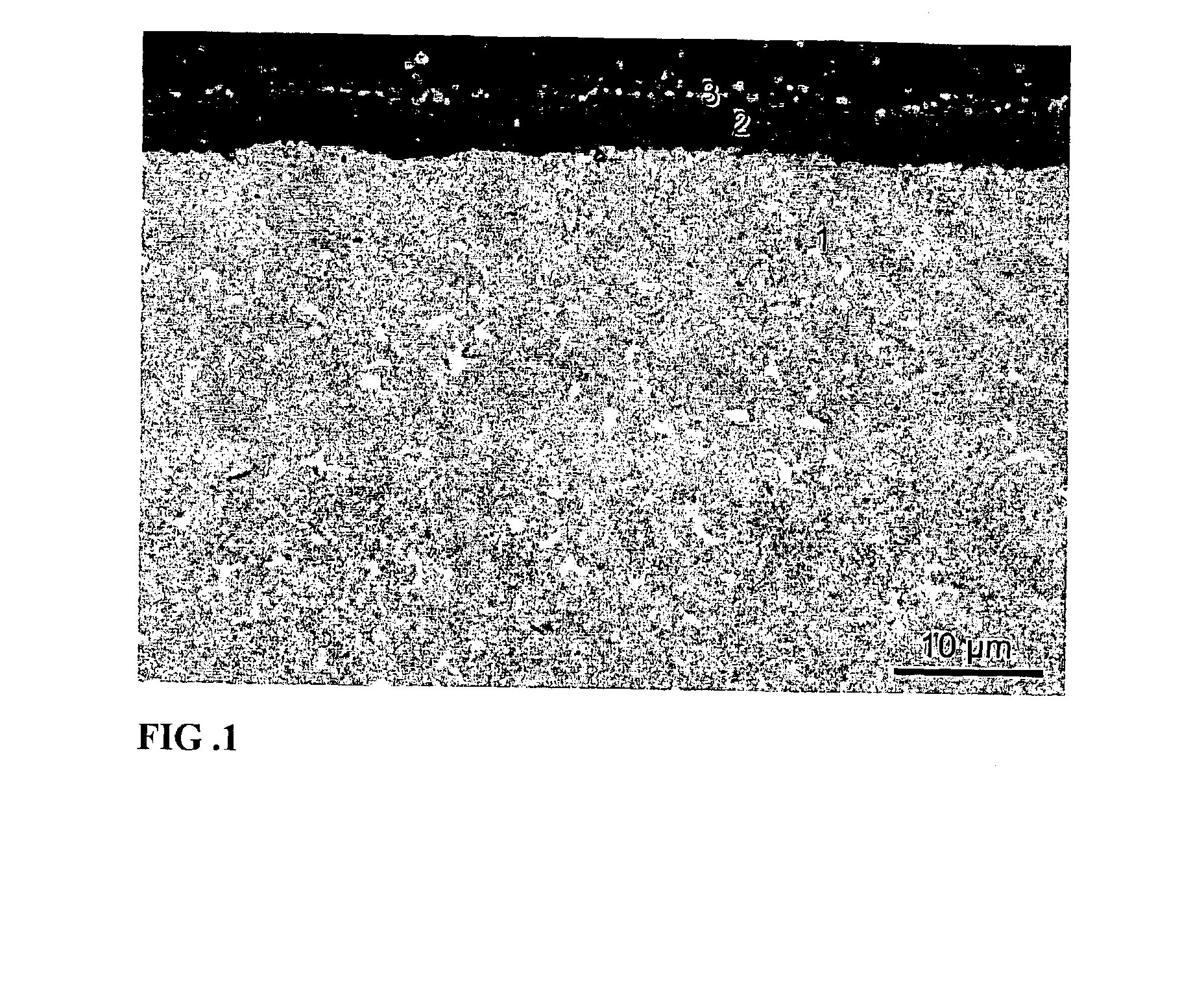
[0027]Grade A: A cemented carbide substrate in accordance with the invention with the composition 8.2 wt % Co, 1.2 wt % TaC, 0.2 wt % NbC and balance WC, with a binder phase alloyed with W corresponding to an S-value of 0.87 was produced by conventional milling of the powders, pressing of green compacts and subsequent sintering at 1430° C. Investigation of the microstructure after sintering showed that the mean intercept length of the tungsten carbide phase was 0.7 μm. The substrate was coated in accordance with the invention in an arc evaporation system. Before coating the inserts were degreased in an ultrasonic cleaning line and in situ sputter cleaned with Ti and Ar ions. During deposition, the inserts were attached to a threefold rotating fixture which was negatively biased. Ti and alloyed Ti—Al metal targets were used and the deposition was made in a N2 containing gas mixture. The temperature was kept at 500° C. during the one hour deposition cycle. Two subsequent layers were d...
example 2
[0031]Grade C: A substrate according to grade A (according to the invention). The substrate was CVD coated with four subsequent layers deposited during the same coating cycle. First a 0.3 μm thick TiCxNyOz layer with zxNyOz deposited at 835-850° C. using MTCVD technique, yielding an approximated carbon to nitrogen ratio x / y=1.5 with z2O3 deposited at approximately 1000° C. and consisting essentially of theκ-phase. Finally a layer of equiaxed nitrogen rich TiCxNyOz with z0.8 was deposited to a thickness of 0.3 μm.
[0032]
OperationCopy millingCutter diameter35 mmWork pieceBar, 350 mm × 270 mmMaterialSS2314, 40 HRCInsert typeRPHT1204Cutting speed200 m / minFeed0.2 mm / toothNumber of teeth3Depth of cut2 mmWidth of cut5-32 mmCoolantNoResultsTool life (min)Grade A (grade according to invention)40Grade C (substrate according to invention)25
[0033]The tool life of both grades was limited by edge chipping. The tool life of Grade C was significantly reduced by adhesive wear leading to pick out of t...
example 3
[0034]Grade D: A substrate according to grade A (according to the invention). The substrate was coated using PVD technique with two subsequent layers deposited during the same coating cycle: a 3.2 μm thick TixAlyN layer with x / y=1.63 followed by a 0.2 μm thick TiN layer.
[0035]
OperationFace millingCutter diameter100 mmWork pieceBar, 75 mm × 600 mmMaterialSS2244, 250 HBInsert typeSEKN1203Cutting speed250 m / minFeed0.25 mm / toothDepth of cut2.5 mmWidth of cut75 mmCoolantNoResultsTool life (min)Grade A (grade according to invention)21Grade D (prior art)15
[0036]The tool life was limited by flank wear. The better tool life of Grade D was the consequence of the more wear resistant coating according to the invention.
PUM
| Property | Measurement | Unit |
|---|---|---|
| thickness | aaaaa | aaaaa |
| thickness | aaaaa | aaaaa |
| mean intercept length | aaaaa | aaaaa |
Abstract
Description
Claims
Application Information