Organic EL element

a technology of organic el and el elements, which is applied in the direction of discharge tube luminescnet screen, other chemical processes, separation processes, etc., can solve the problems of affecting the life of products, unable to prevent the genus and growth of dark spots in the el device, and unable to visually observe the non-light emitting portion

Inactive Publication Date: 2005-05-03
FUTABA CORPORATION
View PDF4 Cites 56 Cited by
  • Summary
  • Abstract
  • Description
  • Claims
  • Application Information

AI Technical Summary

Benefits of technology

[0022]Accordingly, an object of the present invention is to provide a thin-profile organic EL device in which a water-capturing medium is placed by a simple process irrespective of the sealing part, because a lipophilic water-capturing medium layer of organic pigment is formed in a given pattern in the inner surface of hydrophilic sealing cap, in which is placed a thin film of lipophilic water-capturing medium.

Problems solved by technology

It is generally known that a principal problem of the organic EL device is an improvement of the durability of the light emitting part.
When the diameter of the non-light emitting portion grows up in several tens μm and above, the non-light emitting portion can be visually observed and damages the lifetime of product.
However, it is not possible to prevent the dark spot from generating and growing in the EL device at present, because the moisture can not be removed completely.
As described above, the principal problem for the organic EL device is that the moisture inside the container is removed completely to eradicate the dark spot or a small dark spot is not made to grow so as to prolong the life of the EL device.
Accordingly, if the calcium oxide powder of the drying agent 47 falls on the cathode 46 of the emitting part to adhere to it, aluminum and calcium oxide reacts with water on the cathode, which results in generation of corrosion of thin film cathode 46 made of aluminum.
Further, a large space is required for sealing the drying agent and the thickness of the sealing cap 43 must be large.
As a result, the entire thickness of the organic EL device becomes large.
That is to say, such conventional powdered drying agent is extremely poor in workability.
Further, there has been a problem that air incorporated between powders of the drying agent causes a dark spot to grow due to oxygen in air.
Furthermore, if the generation of the dark spot in the vicinity of the central portion of a display area can be suppressed by a drying member of the sealing cap 43, the generation and growth of the dark spot caused by water permeated from an adhesive layer in the peripheral portion near the sealing part can not be sufficiently suppressed.
This is because the sealing part in the peripheral portion of the organic EL device is distant from the drying agent 47 and that it is difficult to select adhesive reliable for different types of materials in the case of bonding the metal cap 43 with the glass board 42.
Since a glass plate is hydrophilic, the water-capturing medium is not compatible with the glass.
It was, therefore, not easy to form a thin film pattern.
Therefore, such a method has a problem that water permeates from the sealing part after being sealed, and a process for removing the water-capturing medium of the sealing area is required.
Such a method has problems that long processing time is required and that it not only adversely affects on health of workmen, but also requires management and processing of waste liquor, because the strong acid of hydrofluoric acid is used for etching glass.
Further, a part of glass plate is cut or scratched by such a spot facing processing.
Therefore, this method is not advantageous in that the total thickness of the organic EL device becomes large and that costs such as material cost, manufacturing cost rise drastically.

Method used


Image

  • Organic EL element
  • Organic EL element
  • Organic EL element

Examples


example 1

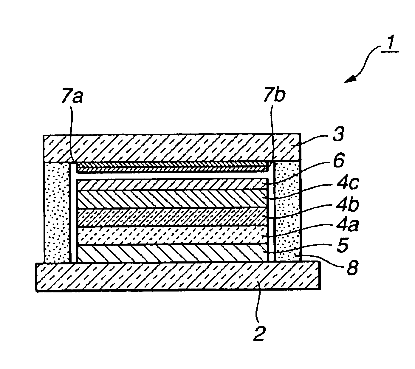
[0079]As shown in FIG. 1, the organic EL device 1 is comprised of a sealed container which is formed by sealing hermetically the rectangular flat plate of glass substrate 2 with the glass-made sealing cap 3 placed opposite to the glass substrate 2 by means of adhesive 8 of sealing part. The 200 nm thick anode 5 by ITO film as a transparent conductive material were formed by a sputtering method on the whole surface of the glass substrate 2 which was a part of the sealing container. Patterning is performed in the shape of anode by a photolithography method to form the anode 5. A part of the anode 5 as an electrode was lead to the end of the glass substrate 2, which was connected as a lead electrode to a drive circuit (not shown).

[0080]An organic emitting layer was formed on the top surface of the anode 5. The organic emitting layer has a three-layer laminated structure comprising the hole injection layer 4a, the hole transportation layer 4b and the emitting-electron-transportation lay...

example 2

[0087]In Example 2, the water-capturing medium used in Example 1 was used in combination with calcium oxide (CaO) which is conventional inorganic water-capturing medium. Since the structure of the organic EL device 1 is the same as that of Example 1, Example 2 is described by referring to FIG. 1. Since the glass board 2 and the organic emitting part on the glass board 2 are the same as those of Example 2, descriptions will be omitted.

[0088]A flat glass plate for a sealing cap was cleaned and put into a vacuum evaporation apparatus. Then, 3 nm thick film of phthalocyanine blue-CuPc, organic pigment, was vacuum-evaporated on the inner side portion of the sealing cap as the water-capturing layer 7a by the use of an evaporation mask. Thereafter, a vacuum evaporation apparatus was filled with dried nitrogen to release vacuum, and the sealing cap was transferred to a glove box filled with dried nitrogen without being exposed to air. Then, a dispersion type-water-capturing medium was made ...

example 3

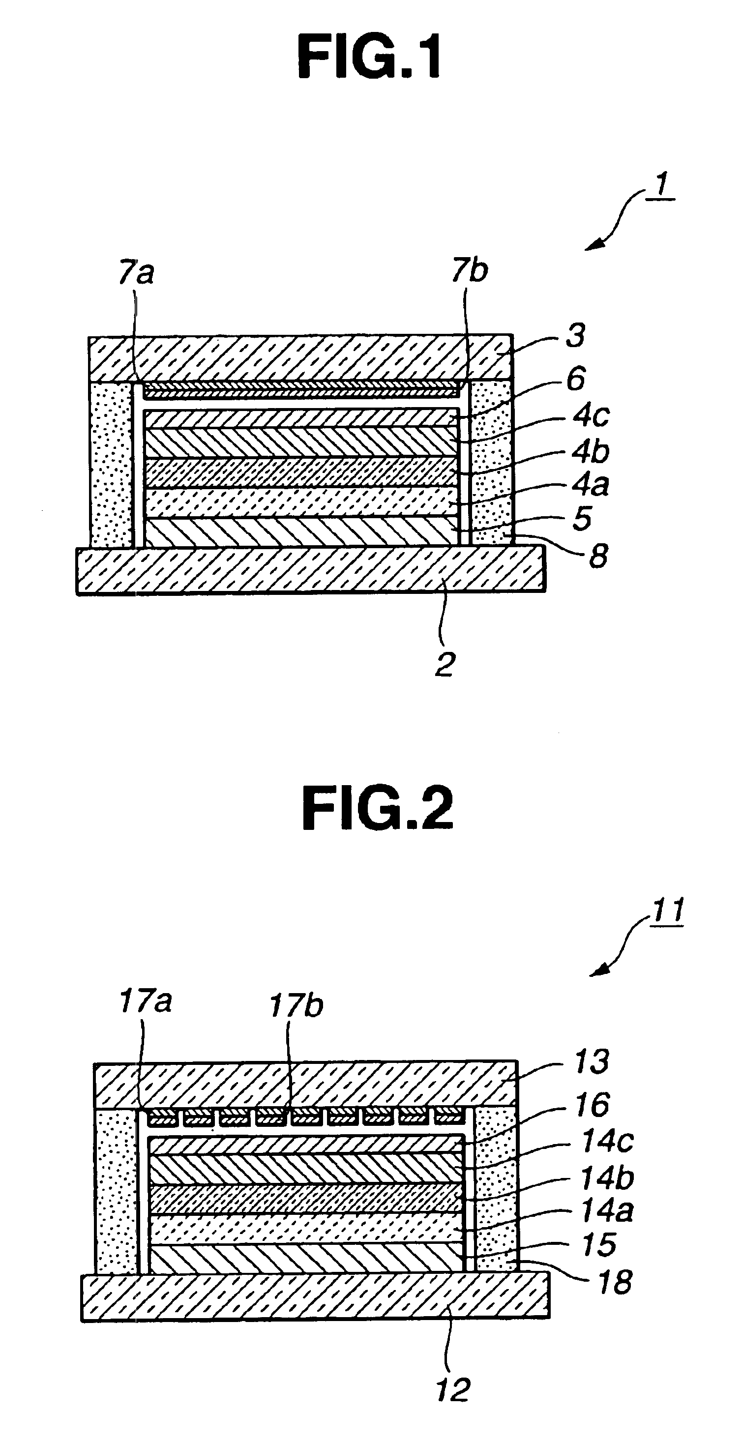
[0092]In Example 2, as shown in FIG. 2, the organic emitting layer for white light emission and the water-capturing medium holding layer formed in three colors pattern, that is, red R, green G and blue B were formed, and the sealing cap was functioned as R, G and B filter.

[0093]The sealing cap 13 was formed by vacuum-evaporating the water-capturing medium holding layer 17a having colors R, G and B on the same flat glass plate as that of Example 1, and patterning organic pigments of R, G and B in given shape by a mask-evaporation method, respectively. Examples of organic pigment of red R are alizarine red, quinacridone red, naphthol red, monoazo red, polyazo red, perylene red, anthraquinolyle red, diketopyrrolopyrrole red and the like. Examples of organic pigment of green G are phthalocyanine green, sap green and the like. Examples of organic pigment of blue B are phthalocyanine blue etc.

[0094]Thereafter, the vacuum evaporation apparatus was filled with dried nitrogen to release vacu...


PUM

PropertyMeasurementUnit
depthaaaaaaaaaa
humidityaaaaaaaaaa
temperatureaaaaaaaaaa

Abstract

An organic EL device having a drying medium capable of suppressing the growth of a dark spot equipped with a water-capturing medium layer for chemically capturing water placed on a water-capturing medium holding layer. The organic EL device is comprised of a sealed container having a glass substrate and a sealing cap bonded to the glass substrate. The sealed container is provided with a light emitting region formed on the substrate which is formed of organic EL material layers placed between a pair of opposite anode and cathode electrodes. The sealed container further includes a water-capturing medium holding layer provided on an inner surface of the container spaced apart from the light emitting region and a water-capturing medium holding layer.

Description

BACKGROUND OF THE INVENTION[0001]1. Field of the Invention[0002]The present invention relates to an organic EL device, and more particularly, to an improvement of a water-capturing medium placed in the organic EL device in order to maintain stable emitting characteristics which are not affected by water or oxygen for a long period of time.[0003]2. Description of the Prior Art[0004]In general, the organic EL has an emitting part having a laminate structure which is formed by interposing a thin film of organic EL layer containing phosphor organic compound between an anode and a cathode. A hole and an electron are injected into the phosphor organic compound to recombine to generate an exciton. The organic EL device is a spontaneous light-emitting device using emission of light (fluorescence / phosphorescence) when the exciton is inactivated.[0005]It is generally known that a principal problem of the organic EL device is an improvement of the durability of the light emitting part. One of ...

Claims


Application Information

Patent Timeline
Patent Type & Authority Patents(United States)
IPC IPC(8): H01L51/52H01L51/50H05B33/04B01D53/28B01J20/22B01J20/26
CPCH01L51/5237H01L51/5036Y10T428/239Y10S428/917Y10T428/23H01L2251/5315H10K50/125H10K50/846H10K50/841H10K2102/3026H05B33/04
Inventor HIEDA, SHIGERUTSURUOKA, YOSHIHISATAKAHASHI, HISAMITSUTANAKA, SATOSHI
Owner FUTABA CORPORATION
Why Eureka
Try Eureka