Method for delivering a fluid to the coronary ostia

a technology of coronary ostia and fluid delivery, which is applied in the direction of contraceptive devices, other blood circulation devices, catheters, etc., can solve the problems of obscuring the surgical site, affecting the patient's recovery, and many cardiac surgery procedures cannot be effectively performed on a beating heart. achieve the effect of maintaining cardioplegic arres

Inactive Publication Date: 2005-07-05
EDWARDS LIFESCIENCES LLC
View PDF70 Cites 91 Cited by
  • Summary
  • Abstract
  • Description
  • Claims
  • Application Information

AI Technical Summary

Benefits of technology

[0013]The present invention provides methods, systems and devices for inducing cardioplegic arrest and for isolating the coronary arteries from the systemic circulation to maintain cardioplegic arrest during cardiac surgery. The devices take the form of one or more arterial catheters for introducing cardioplegic solution by direct antegrade perfusion into the coronary arteries and for occluding the coronary ostia so that blood from the systemic circulation cannot enter the coronary arteries. The catheters, when combined with a cardiopulmonary bypass system, create a total cardiopulmonary bypass and myocardial protection system. When a minimally invasive cardiopulmonary bypass system, such as a femoral-to-femoral cardiopulmonary bypass system, is used, total cardiopulmonary support is achieved without the need for grossly invasive surgical access to the heart.
[0017]In one alternate embodiment, the catheter may be made with a separate distal branch for venting blood from the left ventricle. This venting branch does not have an occlusion device, but instead has an atraumatic distal tip with one or more vent holes which can be safely passed across the aortic valve to vent blood from the left ventricle through a venting lumen in the catheter. The atraumatic distal tip can have a soft blunt end, a bulbous tip, or a curve such as a pigtail that can cross the valve without damaging it. The venting branch should have a small enough outer diameter that it can positioned across the aortic valve without rendering it incompetent.
[0018]In a second preferred embodiment, the invention provides a system of separate arterial catheters, one for each coronary ostium and, optionally, a separate catheter for venting the left ventricle. Each of the coronary perfusion catheters has an inflatable balloon cuff or other occlusion device at the distal end. A perfusion lumen exits each coronary perfusion catheter distal to the occlusion device. The distal ends of each of the coronary perfusion catheters can be preshaped to selectively enter its respective coronary ostium, or each of the coronary catheters can be individually directed into its respective coronary ostium using a steerable guidewire support system. If the catheters are made with selective coronary curves, the catheter shafts should be reinforced or made rigid enough that they can be manipulated into the coronary ostia using selective catheterization techniques. The venting catheter has an atraumatic distal tip and a port near the distal end that is connected to a venting lumen that runs the length of the catheter. Preferable, the catheters can all be introduced through a single arterial sheath placed in the femoral artery or another peripheral artery by arterial cutdown or by the Seldinger technique. To reduce the number of arterial access ports that need to be made, the arterial sheath can be made integral with the arterial cannula of the cardiopulmonary bypass system. One or more hemostasis valves in the arterial cannula allow the coronary and venting catheters to pass through the blood flow lumen of the arterial cannula without leakage of blood.
[0019]In a third preferred embodiment, the invention provides a system of individual arterial catheters which are delivered to the ascending aorta through a single common guiding catheter. The arterial catheters include one catheter for each coronary ostium and, optionally, a separate catheter for venting the left ventricle. The guiding catheter is preferably made with a reinforced shaft to give the system support, and the distal portion of the shaft is preferably curved to hold the distal end of the catheter in the ascending aorta close to the coronary ostia. Since the individual catheters are supported in the aorta by the common guiding catheter, the construction of the individual catheters can be made simpler without reinforcement, possibly reducing the overall expense of the system.
[0020]In each embodiment, the coronary perfusion catheters are preferably combined with a cardiopulmonary bypass system to provide total cardiopulmonary support for the patient undergoing heart surgery. A femoral-to-femoral cardiopulmonary bypass system or other minimally invasive system is preferred to reduce the necessity for invasive access to the heart. A perfusion pump, such as a roller pump, or a pressure cuff can be added to the system to pump the cardioplegic solution through the perfusion catheters, or a syringe can be used. One or more syringes filled with saline solution or with radiopaque contrast diluted with saline can be used to inflate the occlusion balloon cuffs on the perfusion catheters. A stopcock attached to each syringe can be used to keep the balloons inflated for the duration of the surgical procedure.

Problems solved by technology

Many cardiac surgery procedures cannot be effectively performed on a beating heart because the motion of the heart muscle would interfere with the intricate surgical manipulations.
Also, for procedures where the coronary arteries or one of the chambers of the heart must be opened, the blood pressure in the beating heart would cause excessive bleeding that would endanger the patient and obscure the surgical site.
If the perfusion is being done by injection into the aortic root or into the coronary arteries, this usually requires interrupting the surgery while the cardioplegic solution is infused.
This lengthens the overall procedure and the amount of time that the patient must be kept on cardiopulmonary bypass.
Complete perfusion of the myocardium is also not assured when the coronary arteries are highly collateralized.
The lower perfusion pressure means that it can take up to thirty minutes to deliver the recommended 500-1000 ml of cardioplegic solution by retrograde perfusion and, consequently, it takes longer to induce cardioplegic arrest.
However, by requiring two sets of perfusion cannulae, this procedure introduces additional complications and potentially increases the risk of mechanical injury to the vessels involved.
It also does nothing to solve an additional major problem shared by both antegrade and retrograde cardioplegia techniques, that of the necessity to cross clamp the ascending aorta to isolate the coronary arteries from the arterial circulation.
However, when the procedure being performed does not otherwise require opening the chest, the necessity of opening the chest for the sole purpose of placing the aortic cross clamp introduces significant trauma and risk of complication which might be avoided.
Current methods of administering cardioplegia and establishing cardiopulmonary bypass do not meet this need.
Even though femoral-to-femoral cardiopulmonary bypass systems have been available for many years, these systems cannot achieve total bypass of the heart without aortic cross clamping to isolate the coronary arteries from the systemic circulation.
The continuing need for invasive aortic cross clamping is a major obstacle to achieving the goal of performing cardiac surgery through minimally invasive surgical techniques.

Method used


Image

  • Method for delivering a fluid to the coronary ostia
  • Method for delivering a fluid to the coronary ostia
  • Method for delivering a fluid to the coronary ostia

Examples


first embodiment

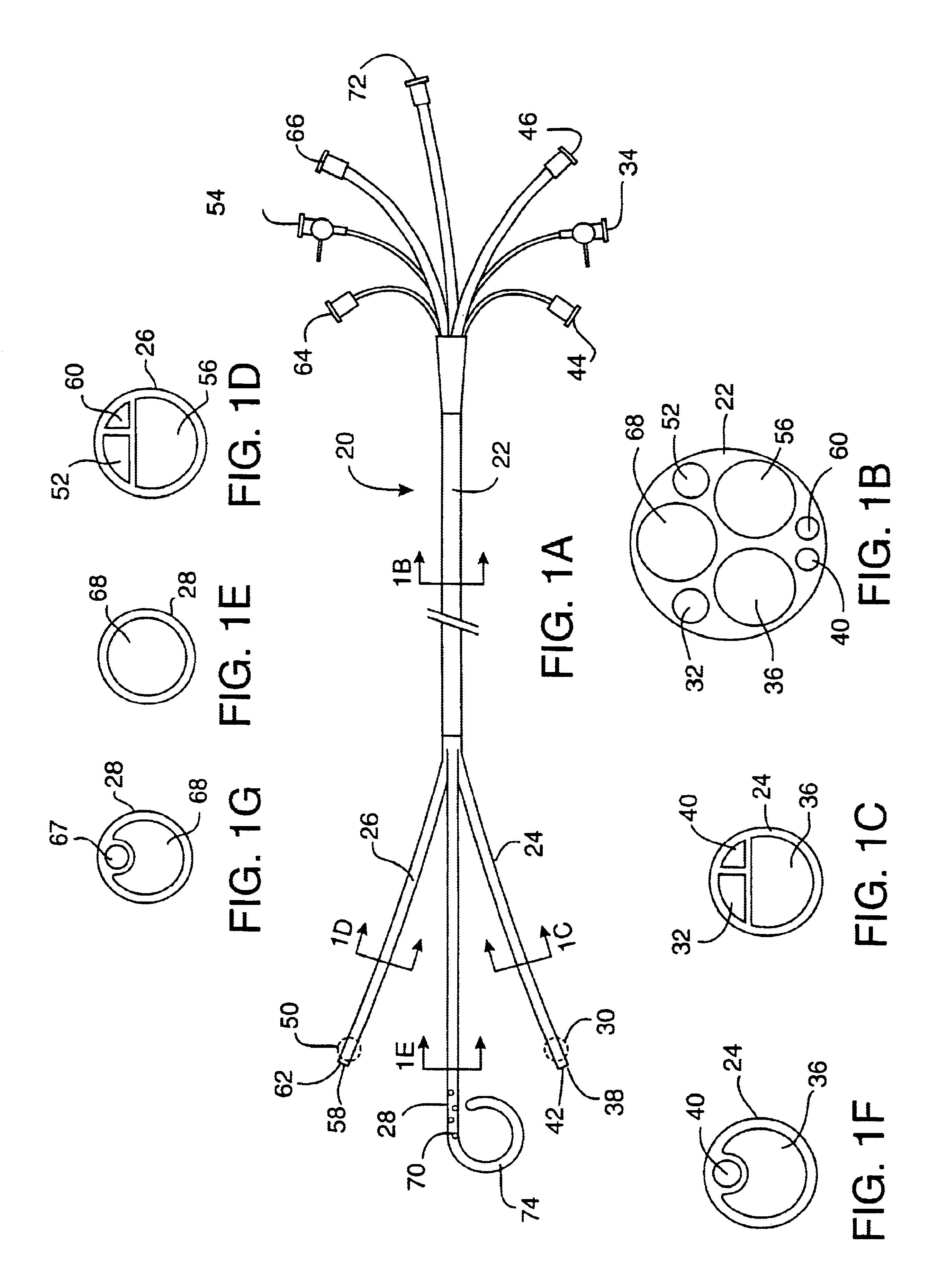
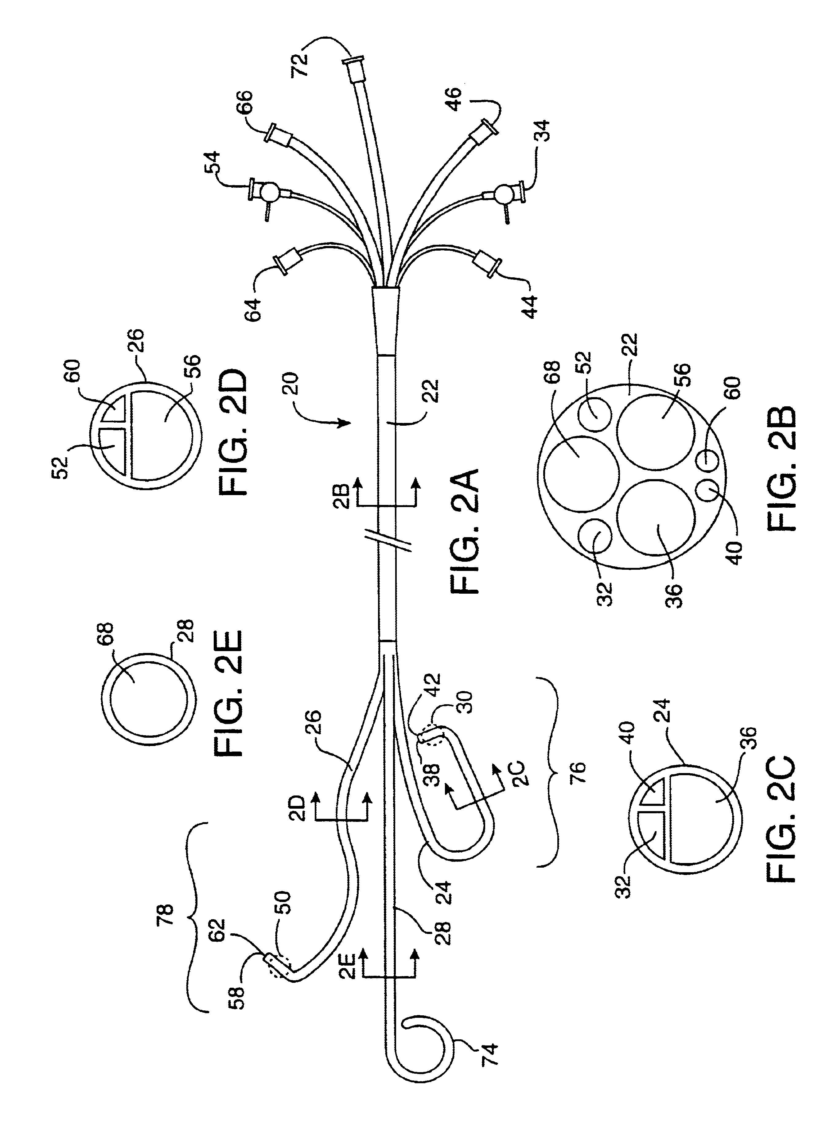
[0036]FIGS. 1A-1E illustrate the coronary perfusion catheter for use in the method of the present invention. In this embodiment, a single arterial catheter 20 is used to deliver cardioplegic solution to all of the coronary arteries. A side elevation view of the catheter 20 is shown in FIG. 1A. The single catheter 20 has an elongated shaft 22 and a plurality of distal branches 24, 26, 28 which are adapted for selective intubation and occlusion of each of the coronary ostia. In this illustrative example, the catheter includes a first distal branch 24 for engaging the left coronary ostium, and a second distal branch 26 for engaging the right coronary ostium. The catheter is also shown with an optional third distal branch 28 for venting blood from the left ventricle of the heart. All three of the distal branches join together to form a common proximal shaft 22.

[0037]The first distal branch 24 of the catheter has a first inflatable occlusion balloon cuff 30 at its distal tip. The balloon...

third embodiment

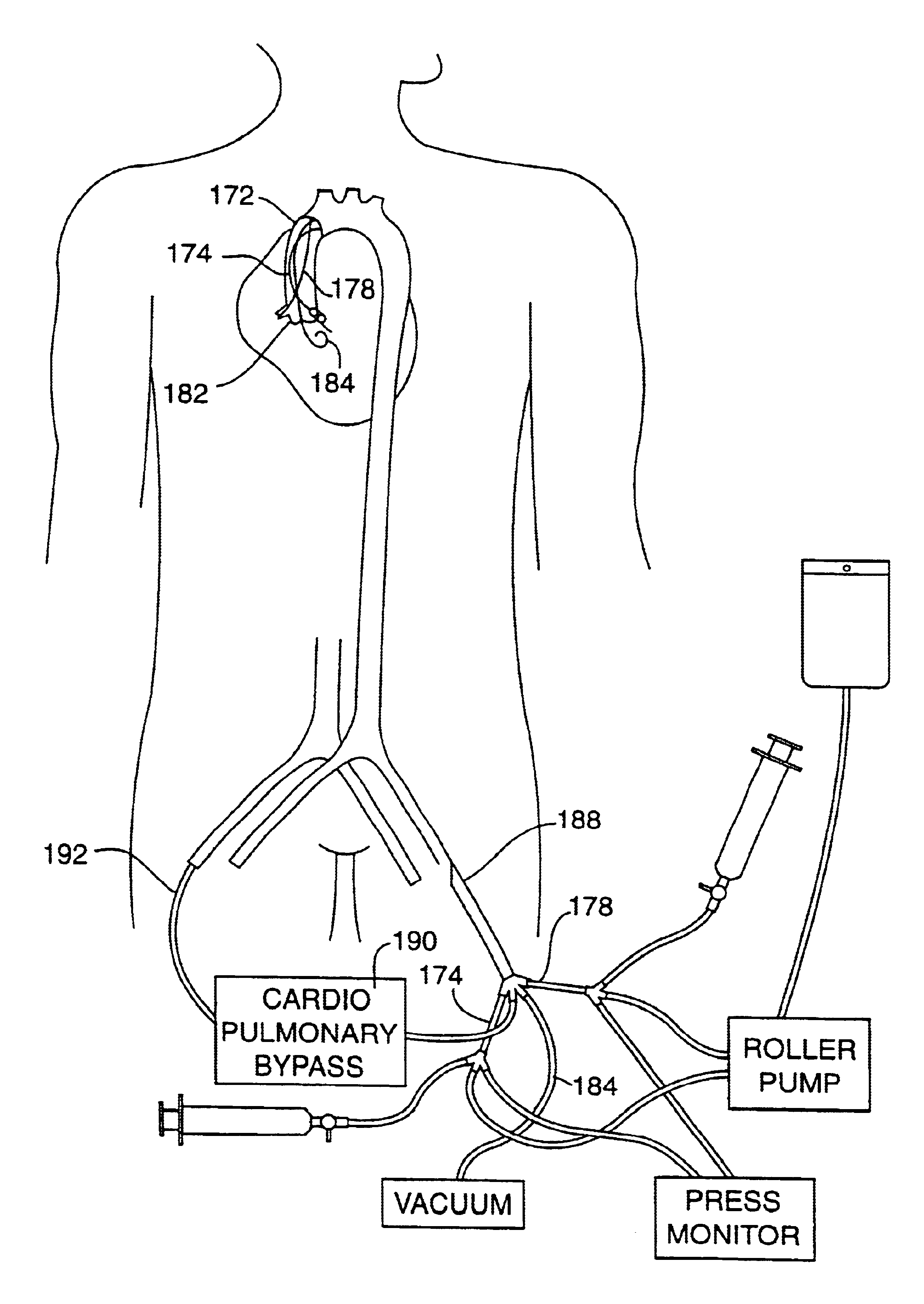
[0060]The perfusion catheters 174, 178 can be placed with fluoroscopic guidance by either of two methods. In the first method, the distal ends of the catheters are preshaped with selective coronary curves. The curves are straightened out with a stiff guidewire placed in the perfusion lumen, as shown by phantom lines 82′, 84′ in FIG. 4A, when the catheters are introduced into the femoral artery and advanced through the descending aorta and into the ascending aorta. When the guidewires are withdrawn the catheters resume their curved shapes which are adapted to be easily maneuvered into the coronary ostia. In the second method, the distal ends of the catheters are not precurved, but a curved steerable guidewire is used to direct each of the catheters into the respective coronary ostium. With the catheter system, illustrated in FIGS. 5A-5B, the curved guiding catheter can assist the steerable guidewire in directing the perfusion catheters to their respective coronary ostia. Alternativel...


PUM


Abstract

A catheter system is provided for accessing the coronary ostia transluminally from a peripheral arterial access site, such as the femoral artery, and for inducing cardioplegic arrest by direct infusion of cardioplegic solution into the coronary arteries. In a first embodiment, the catheter system is in the form of a single perfusion catheter with multiple distal branches for engaging the coronary ostia. In a second embodiment, multiple perfusion catheters are delivered to the coronary ostia through a single arterial cannula. In a third embodiment, multiple perfusion catheters are delivered to the coronary ostia through a single guiding catheter. In a fourth embodiment, multiple catheters are delivered to the coronary ostia through a single guiding catheter which has distal exit ports that are arranged to direct the perfusion catheters into the coronary ostia. In each embodiment, the catheters are equipped with an occlusion means at the distal end of the catheter for closing the coronary ostia and isolating the coronary arteries from the systemic blood flow. The occlusion means can take the form of an inflatable occlusion balloon cuff, a tapered occlusion device or an O-ring encircling the distal end of the catheter. An optional ventricular venting catheter can be included in the system for venting blood and fluids from the left ventricle of the heart. The catheter system is combined with a femoral-to-femoral cardiopulmonary bypass system to provide a system for cardioplegic arrest and total cardiopulmonary support during minimally invasive cardiac surgical procedures.

Description

CROSS-REFERENCE TO RELATED APPLICATIONS[0001]This application is a continuation of U.S. patent application Ser. No. 09 / 151,582, filed Sep. 11, 1998, now abandoned, which is a division of application Ser. No. 08 / 615,152, filed Mar. 12, 1996, now issued as U.S. Pat. No. 5,807,308, which is a divisional of application Ser. No. 08 / 351,850, filed Dec. 7, 1994, now issued as U.S. Pat. No. 5,695,457. The complete disclosures of the forementioned related U.S. patent applications are hereby incorporated herein by reference for all purposes.FIELD OF THE INVENTION[0002]The present invention relates generally to methods and devices for performing surgical procedures. More particularly, it relates to methods and devices for inducing cardioplegic arrest for myocardial protection during cardiac surgery by direct perfusion of the coronary arteries using a transluminal approach from a peripheral arterial entry point.BACKGROUND OF THE INVENTION[0003]Myocardial protection is an essential part of almos...

Claims


Application Information

Patent Timeline
Patent Type & Authority Patents(United States)
IPC IPC(8): A61M25/06A61M25/00A61M25/10A61B17/00A61F2/24A61F2/958A61M1/36A61M25/01A61M25/14A61M29/02
CPCA61F2/2427A61M1/3653A61M25/0041A61M25/0068A61M25/01A61M25/0662A61M25/10A61M1/3659A61B2017/00243A61B2018/00232A61B2018/00261A61M25/005A61M25/008A61M25/0125A61M25/1002A61M2025/0031A61M2025/0034A61M2025/0036A61M2025/004A61M2025/0057A61M2025/0078A61M2025/0087A61M2025/028A61M2025/1047A61M2025/1077A61M2205/11A61M2205/366A61M2210/125A61M1/3613A61M2202/047
Inventor ST. GOAR, FREDERICK G.PETERS, WILLIAM S.EVARD, PHILIP C.BOYD, STEPHEN W.ADAMS, CRAIG L.MUELLER, JR., RICHARD L.STEVENS, JOHN H.
Owner EDWARDS LIFESCIENCES LLC
Why Eureka
Try Eureka