
Optical device, laser beam source, laser apparatus and method of producing optical device

Inactive Publication Date: 2005-07-05
PANASONIC CORP
View PDF42 Cites 1 Cited by
  • Summary
  • Abstract
  • Description
  • Claims
  • Application Information

AI Technical Summary

Benefits of technology

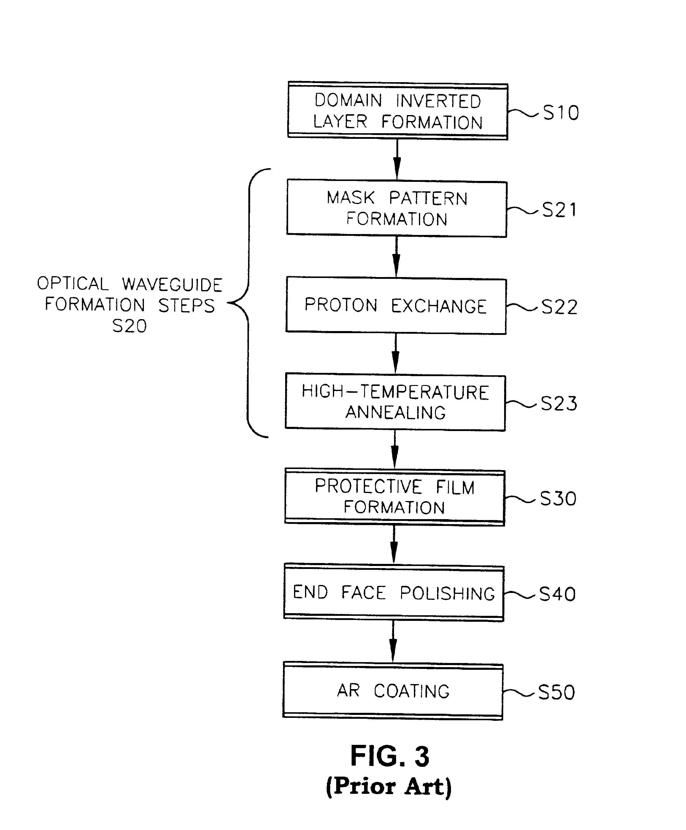
[0252]As described above, in the optical wavelength conversion element of the present invention, after an optical element is produced in an LiNbXTa1-XO3 (0≦X≦1) substrate, low-temperature annealing is performed so as to repress an increase in refractive index generated during a heat treatment such as high-temperature annealing, and then, a stable proton exchange layer is formed, whereby a stable optical element can be formed. Particularly, the present invention is indispensable for putting into practical use an optical wavelength conversion element whose phase-matched wavelength varies with refractive index variation.
[0255]Furthermore, with the laser light source of the present invention, the optical wavelength conversion element section can be made very compact by designing it so that pumped light or a fundamental wave propagates through a fiber. Furthermore, it is possible to remotely dispose the optical wavelength conversion element away from the heat generated by the semiconductor laser and thus to prevent temperature variation, whereby a high output semiconductor laser can be used.
[0256]Moreover, if periodic domain inverted structures are used as the optical wavelength conversion element, in addition to a significantly improved conversion efficiency, modulation can be easily effected by applying a low voltage, thereby presenting an industrial advantage. Thus, a modulator can be integrated, whereby it is possible to achieve smaller size, lighter weight and lower cost. Furthermore, by employing an optical waveguide with a weak confinement as the optical wavelength conversion element, the concentration of a harmonic wave becomes small, whereby the optical damage is considerably improved. This is because, a 100 times larger area with respect to that in a conventional technique can tolerate a 100 times greater optical damage. Furthermore, with the laser light source of the present invention, it is possible to use a high output semiconductor laser of a multi-stripe or wide-stripe type by converting pumped light to a fundamental wave using a solid state laser crystal, whereby it is possible to obtain a high output harmonic wave.
[0257]Because of these factors, it is possible, for example, to obtain a total conversion efficiency of 20% by amplifying the electro-optical conversion efficiency of the semiconductor laser of 30% with the conversion efficiency of an optical wavelength conversion element of 70%. Moreover, by RF superimposing a semiconductor laser in the laser light source of the present invention, the conversion efficiency is improved by 5-fold, for example, as compared to the case when the RF superimposition is not performed.
[0258]Furthermore, with the laser projection apparatus of the present invention, since it is based on a semiconductor laser, it is possible to achieve considerably smaller size, lighter weight and lower cost. Moreover, it is possible to simultaneously achieve a smaller size, a lighter weight and a lower cost of the apparatus by using a high output laser light source based on a semiconductor laser and an optical wavelength conversion element. Furthermore, the power consumption can also be extremely low. One of the factors therefor is that the apparatus does not separately has a modulator for laser light, which, instead, is integrated with the optical wavelength conversion element. Furthermore, as compared to a conventional technique, the resolution is considerably improved. For example, as compared to a configuration using a gas laser, considerable improvements are achieved such as a one thousandth weight, a one-thousandth volume and a one-hundredth power consumption. The small size and the low power consumption of the employed laser light source and the integration thereof with the optical modulator greatly contribute to these achievements. That is, this results from that the configuration using a semiconductor laser and an optical wavelength conversion element can be subminiaturized while the efficiency of conversion from an electrical power is higher than that of a gas laser by about two orders of magnitude. Particularly, it is significantly effective to use an element having periodic domain inverted structures as an optical wavelength conversion element, since this makes it possible to improve efficiency and realize integration of the optical modulator driven with a low voltage.
[0259]Furthermore, it is possible to generate the primary colors by allowing fluorescent substances to be irradiated with an ultraviolet laser light source, and thus to achieve an even smaller size and lower cost, thereby presenting a significant industrial advantage. Thus, it is possible to generate the primary colors, i.e., red, green and blue, with a single laser light source. It is also favorable that the dichroic mirror for combining waves can be eliminated.
[0260]Furthermore, when scanning is terminated, the laser projection apparatus of the present invention prevents a certain position from being irradiated with laser light in a concentrated manner, thereby presenting a laser light termination or cutting function. Moreover, if the signal from a sensor is interrupted even for a moment, the power of the laser light source is turned off by a control circuit. Thus, it is safe since a human, etc., never touches the short wavelength laser light having a high output. The safety of this laser projection apparatus is maintained as described above.
[0261]Furthermore, the RF superimposition is effective for a laser projection apparatus using a laser light source based on direct wavelength conversion of a semiconductor laser. This is because a speckle noise can be prevented from being generated, whereby a clear image can be reproduced. Moreover, a speckle noise can also be prevented in the case where red, green or blue laser light is generated directly by semiconductor laser light.

Problems solved by technology

However, the non-linearity of the portions where the proton exchange has been performed (the high refractive index layers), as thus formed, is deteriorated.
Such an optical wavelength conversion element has a problem that the phase-matched wavelength thereof varies with the passage of time, whereby a harmonic wave cannot be obtained.

Method used


Image

  • Optical device, laser beam source, laser apparatus and method of producing optical device
  • Optical device, laser beam source, laser apparatus and method of producing optical device
  • Optical device, laser beam source, laser apparatus and method of producing optical device

Examples


example 1

[0143]Referring to FIG. 7, Example 1 of the present invention will be described.

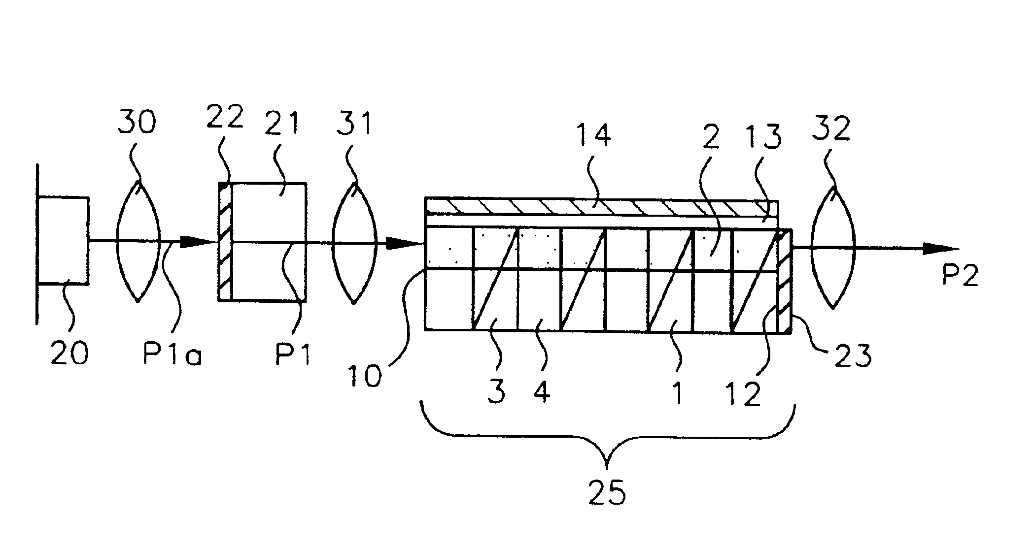
[0144]In an optical wavelength conversion element of the present example, an optical waveguide of a stable proton exchange layer is formed in an LiTaO3 substrate 1, and a plurality of domain inverted layers 3 are periodically arranged along the optical waveguide. By making a fundamental wave P1 incident upon an input end of the optical waveguide, a harmonic wave P2 is emitted from an output end thereof. The length of the optical wavelength conversion element (length of the optical waveguide) is 9 mm in the present example. Moreover, in order to allow for operation at a wavelength of 850 nm, the length of a pitch of the domain inverted layers 3 is set to 3.7 μm.

[0145]Hereinafter, referring to FIGS. 8A to 8E, a production method of the optical wavelength conversion element will be described.

[0146]First, as shown in FIG. 8A, a Ta film is deposited so as to cover the principal surface of the LiTaO3 substrate...

example 2

[0160]Next, Example 2 of the present invention will be described.

[0161]First, a Ta film is deposited so as to cover the principal surface of the LiTaO3 substrate, after which ordinary photolithography and dry etching techniques are used to pattern the Ta film (thickness: about 200 to 300 nm) into a striped pattern, thereby forming the Ta mask. The Ta mask used in the present example has a pattern where strips each 1.2 μm wide and 10 mm long are arranged so as to be equally spaced apart from one another, and the arrangement pitch of the strips is 3.6 μm. A proton exchange process is performed for the LiTaO3 substrate 1 whose principal surface is covered by the Ta mask. The proton exchange process is performed by immersing the surface of the substrate for 20 minutes in a pyrophosphoric acid heated to 260° C. Thus, 0.5μm thick proton exchange layers are formed in portions of the LiTaO3 substrate 1 which are not covered by the Ta mask. Then, the Ta mask is removed by etching for 2 minut...

example 3

[0169]Next, as Example 3 of the present invention, a case of using an LiNbO3 substrate (thickness: 0.4 to 0.5 mm) will be described.

[0170]First, ordinary photolithography and dry etching techniques are used to form a Ta electrode (first Ta electrode) having a pattern similar to the pattern of the Ta mask used in the above-described examples on the principal surface of the LiNbO3 substrate.

[0171]Then, a Ta film (second Ta electrode) is deposited on the entire reverse surface of the substrate. The first Ta electrode formed on the principal surface of the substrate and the second Ta electrode formed on the reverse surface of the substrate form an electrode structure for applying an electric field across the substrate.

[0172]Next, a voltage (e.g., 10 kilovolts) is applied between the first Ta electrode and the second Ta electrode so as to form an electric field in the LiNbO3 substrate. By the application of an electric field, a domain inverted layer is formed so as to extend from a porti...


PUM


Abstract

After forming domain inverted layers 3 in an LiTaO3 substrate 1, an optical waveguide is formed. By performing low-temperature annealing for the optical wavelength conversion element thus formed, a stable proton exchange layer 8 is formed, where an increase in refractive index generated during high-temperature annealing is lowered, thereby providing a stable optical wavelength conversion element. Thus, the phase-matched wavelength becomes constant, and variation in harmonic wave output is eliminated. Consequently, with respect to an optical wavelength conversion element utilizing a non-linear optical effect, a highly reliable element is provided.

Description

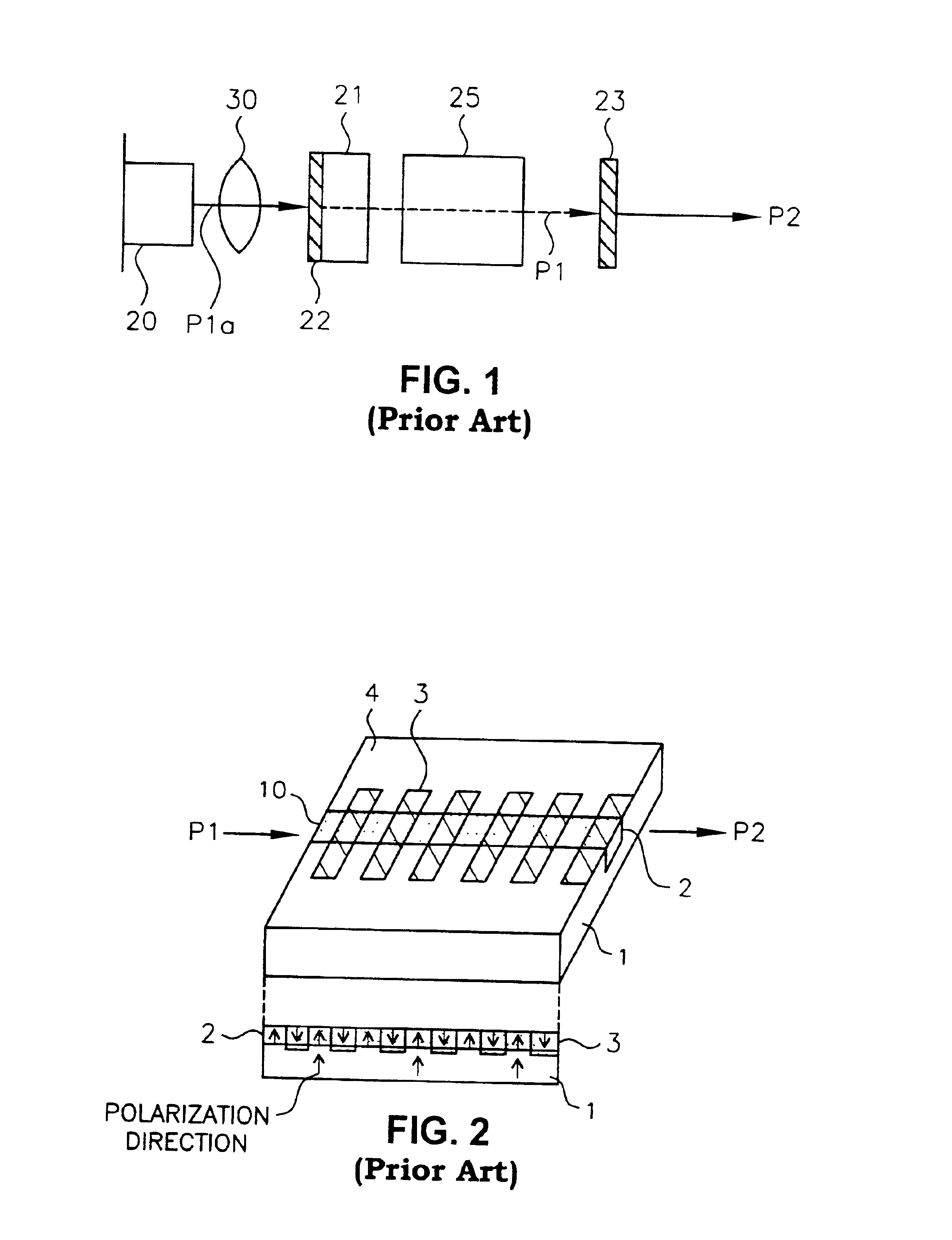
[0001]This application is a divisional of U.S. patent application Ser. No. 08 / 973,380 filed Mar. 16, 1998 now U.S. Pat. No. 6,333,943.TECHNICAL FIELD[0002]The present invention relates to an optical element such as an optical wavelength conversion element, a laser light source and a laser device suitable for use in the field of optical information processing or optical measuring control where coherent light is used, and also relates to a method for producing an optical element.BACKGROUND ART[0003]Referring to FIG. 1, a conventional laser light source using an optical wavelength conversion element will be described. The laser light source is basically composed of a semiconductor laser 20, a solid state laser crystal 21 and an optical wavelength conversion element 25 made of KNbO3, which is a non-linear optical crystal.[0004]As shown in FIG. 1, pumped light P1a emitted from the semiconductor laser 20, which oscillates at 807 nm, is collected by a lens 30 so as to excite YAG as a solid...

Claims


Application Information

Patent Timeline
IPC IPC(8): G02F1/355G02F1/377G02F1/35H01S3/109H01S3/0941
CPCG02F1/3558G02F1/37G02F1/3775H01S3/109H01S5/40G02F2203/60H01S3/09415H01S3/23H01S5/0092H01S5/02H01S5/4087
Inventor YAMAMOTO, KAZUHISAMIZUUCHI, KIMINORIKITAOKA, YASUOKATO, MAKOTO
Owner PANASONIC CORP
Learn More