Apparatus and method for flow of process gas in an ultra-clean environment

a technology of process gas and apparatus, applied in the direction of chemistry apparatus and processes, microstructural devices, coatings, etc., can solve the problems of unrecirculation, achieve high controllable flow rate, reduce, minimize or even eliminate the occurrence of localized areas, improve process gas efficiency and process efficiency

Inactive Publication Date: 2005-09-27
TEXAS INSTR INC +1
View PDF85 Cites 57 Cited by
  • Summary
  • Abstract
  • Description
  • Claims
  • Application Information

AI Technical Summary

Benefits of technology

[0009]The present invention provides improvements in the apparatus and methods used for the etching of layers or areas, or for the addition or deposition of layers or elements, in or on a microstructure. In one such improvement, a recirculating and / or cooling system is introduced into the etch or deposition process to thereby provide a controlled reaction environment while improving the effectiveness of the process gas and the efficiency of the process. Recirculation has not been done in the prior art due to the risk of introducing foreign bodies or substances into the ultra-clean reaction environment and contaminating the sample, a risk that is associated with the use of recirculation pumps. One embodiment of this invention thus resides in the discovery that recirculation can indeed be performed without such risk. Another improvement provided by this invention is the use of an etching or deposition chamber that contains internal structural features that help distribute the incoming process gas over the sample surface. This distribution serves to reduce, minimize, or even eliminate the occurrence of localized areas of high concentration of the process gas and any resulting “hot spots” on the sample surface. Still another improvement is the design and use of a reciprocating pump for recirculating the process gas. The pump fully seals the process gas from the environment without the use of lubricants or of any materials that may contaminate the environment or are susceptible to corrosion by the process gas. The pump nevertheless provides process gas at a highly controllable flow rate to the chamber in which the reaction occurs. Use of the pump thus leads to the reduction of the effluents and an increase in product uniformity. Each of these improvements results in an increase in the efficiency of the process, and to the yield and quality of the product, and each can be used either alone or in combination with one or more of the others.

Problems solved by technology

Recirculation has not been done in the prior art due to the risk of introducing foreign bodies or substances into the ultra-clean reaction environment and contaminating the sample, a risk that is associated with the use of recirculation pumps.

Method used


Image

  • Apparatus and method for flow of process gas in an ultra-clean environment
  • Apparatus and method for flow of process gas in an ultra-clean environment
  • Apparatus and method for flow of process gas in an ultra-clean environment

Examples


example

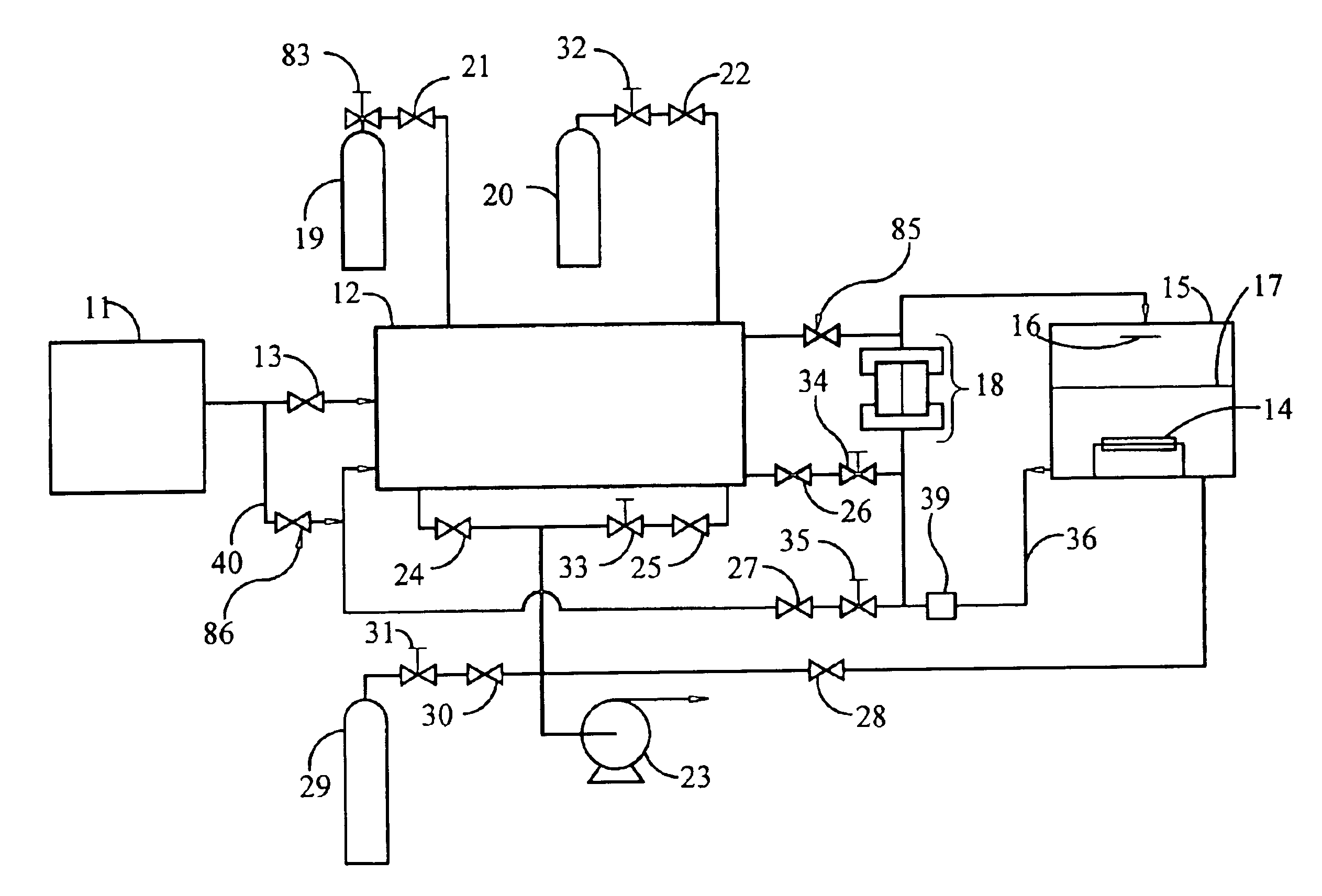
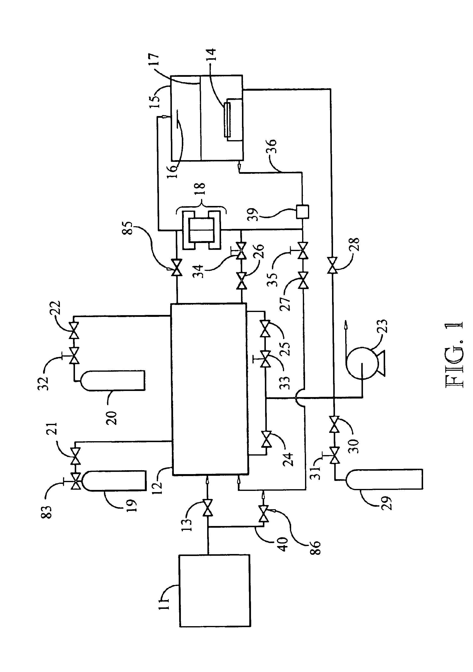
[0066]For etching a 6″ glass substrate with MEMS devices, typical apparatus and process parameters include: double source chamber design with 11a at 28 C, 11b at 31 C and intermediate connector piece at 35 C. Expansion chamber 12 and etch chamber 15 at 23 C. In step 6 above, both chambers 12 and 15 are filled with a mixture of 45 T Nitrogen (N2) and 450 T Helium (He); total gas pressure is 495 T. In step 8, the chamber 12 is filled with XeF2 gas above 4.2 T. In step 9, the XeF2 gas in chamber 12 is reduced to 4 T for use in the process. In step 10, chamber 12 receives 47 T of Nitrogen (N2) and 470 T of Helium (He); total gas pressure in chamber 12 at the end of step 10 is 521 T.

[0067]Sacrificial silicon layers that can be removed using the apparatus and method of this invention may be layers of crystalline silicon, amorphous silicon, partially crystalline silicon, crystalline silicon of multiple crystal sizes, polysilicon in general, and silicon doped with such dopants as arsenic, p...


PUM

PropertyMeasurementUnit
sizeaaaaaaaaaa
sizeaaaaaaaaaa
sublimation pressureaaaaaaaaaa

Abstract

Processes for the addition or removal of a layer or region from a workpiece material by contact with a process gas in the manufacture of a microstructure are enhanced by the use of recirculation of the process gas. Recirculation is effected by a pump that has no sliding or abrading parts that contact the process gas, nor any wet (such as oil) seals or purge gas in the pump. Improved processing can be achieved by a process chamber that contains a baffle, a perforated plate, or both, appropriately situated in the chamber to deflect the incoming process gas and distribute it over the workpiece surface. In certain embodiments, a diluent gas is added to the recirculation loop and continuously circulated therein, followed by the bleeding of the process gas (such as an etchant gas) into the recirculation loop. Also, cooling of the process gas, etching chamber and/or sample platen can aid the etching process. The method is particularly useful for adding to or removing material from a sample of microscopic dimensions.

Description

CROSS REFERENCE TO RELATED APPLICATION[0001]This application is a continuation-in-part of commonly owned, U.S. patent application Ser. No. 09 / 427,841, inventors Patel et al., filed Oct. 26, 1999 now U.S. Pat. No. 6,290,864, the contents of which are incorporated herein by reference.BACKGROUND OF THE INVENTION[0002]1. Field of the Invention[0003]This invention lies in the technology of the manufacture of microstructures, which include such devices as microelectromechanical structures, micro opto-electromechanical structures, and semiconductor devices. In particular, this invention addresses gas-phase etching and deposition procedures, with particular emphasis on those involving the etching of silicon. This invention further addresses apparatus that is especially useful in meeting the needs of gas-phase etching and deposition.[0004]2. Description of the Prior Art[0005]The use of selective etchants to remove sacrificial layers or regions in a multilayer structure without removal of an ...

Claims


Application Information

Patent Timeline
Patent Type & Authority Patents(United States)
IPC IPC(8): B81B3/00C23F1/12C23F1/08C23F1/10C23F1/00H01L21/302C03C15/00C25F3/12H01LH01L21/00
CPCB81C1/00587B81C99/0025B82Y30/00H01L21/67017B81C2201/0138C03C15/00C03C2218/33H01L21/67063H01L21/3065C23F1/08
Inventor PATEL, SATYADEV R.SCHAADT, GREGORY P.MACDONALD, DOUGLAS B.MACDONALD, NILES K.
Owner TEXAS INSTR INC
Why Eureka
Try Eureka