
Vacuum sensor

a vacuum sensor and sensor technology, applied in the field of vacuum sensors, can solve the problems of inability to achieve zero state of sensors located in the chamber, and high cost of devices, so as to simplify calibration, response and detection, and fast and reliable measurements proportional

Inactive Publication Date: 2005-11-15
BROOKS INSTRUMENT
View PDF19 Cites 3 Cited by
  • Summary
  • Abstract
  • Description
  • Claims
  • Application Information

AI Technical Summary

Benefits of technology

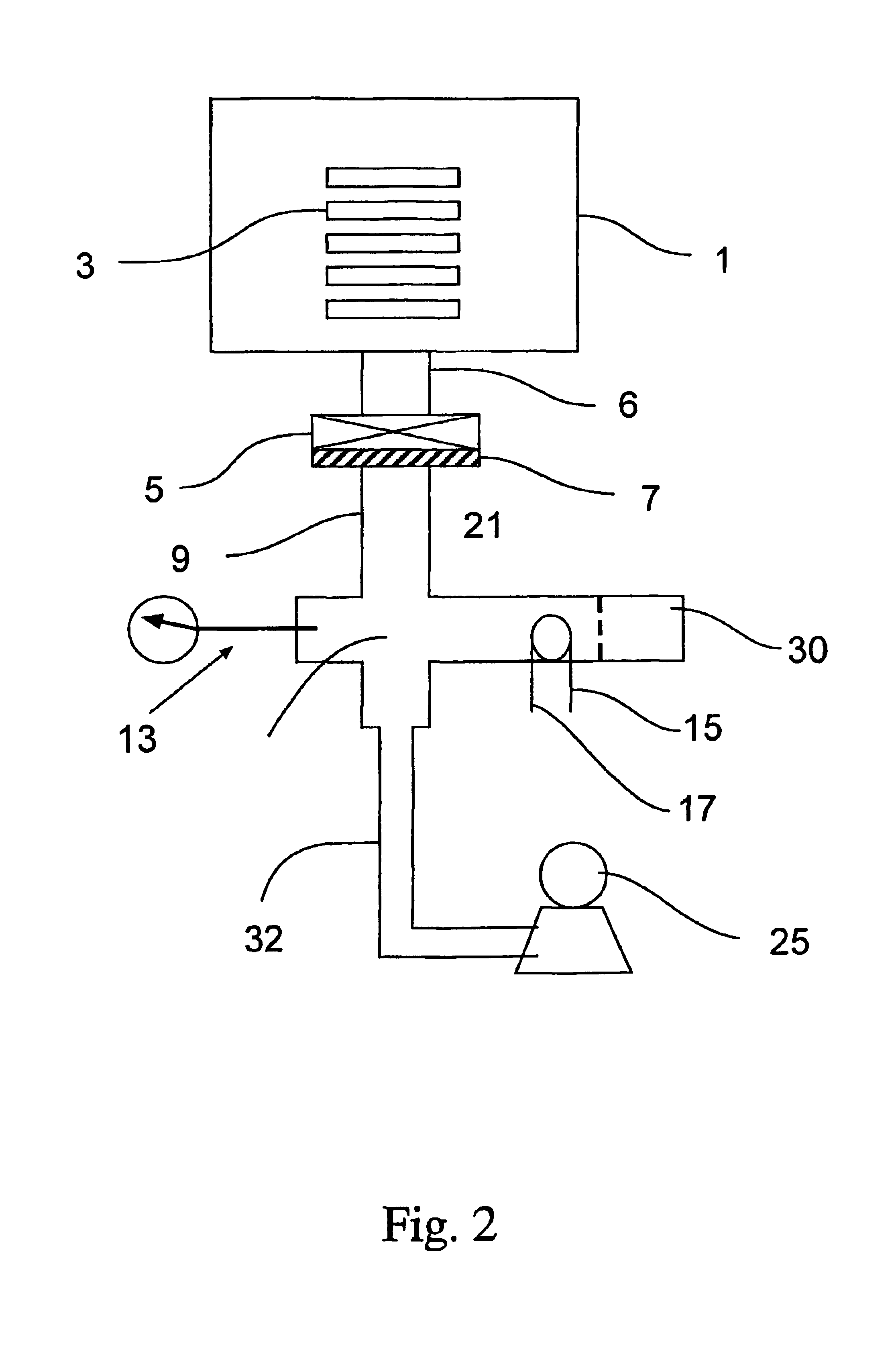
[0019]In a fourth embodiment, an additional volume is provided for the sensor housing located downstream from the sensor to further increase the volume of gas and its time in contact with the sensor. The benefit of such an additional volume is additional contact time of the gas with the sensor. During the time when the sensor and the additional volume are isolated from the main vacuum chamber, gas is removed from the sensor housing and added volume. Upon opening of the isolation valve between the chamber and vacuum pump, gas from the chamber flows to fill in the volume of the sensor and the added volume.
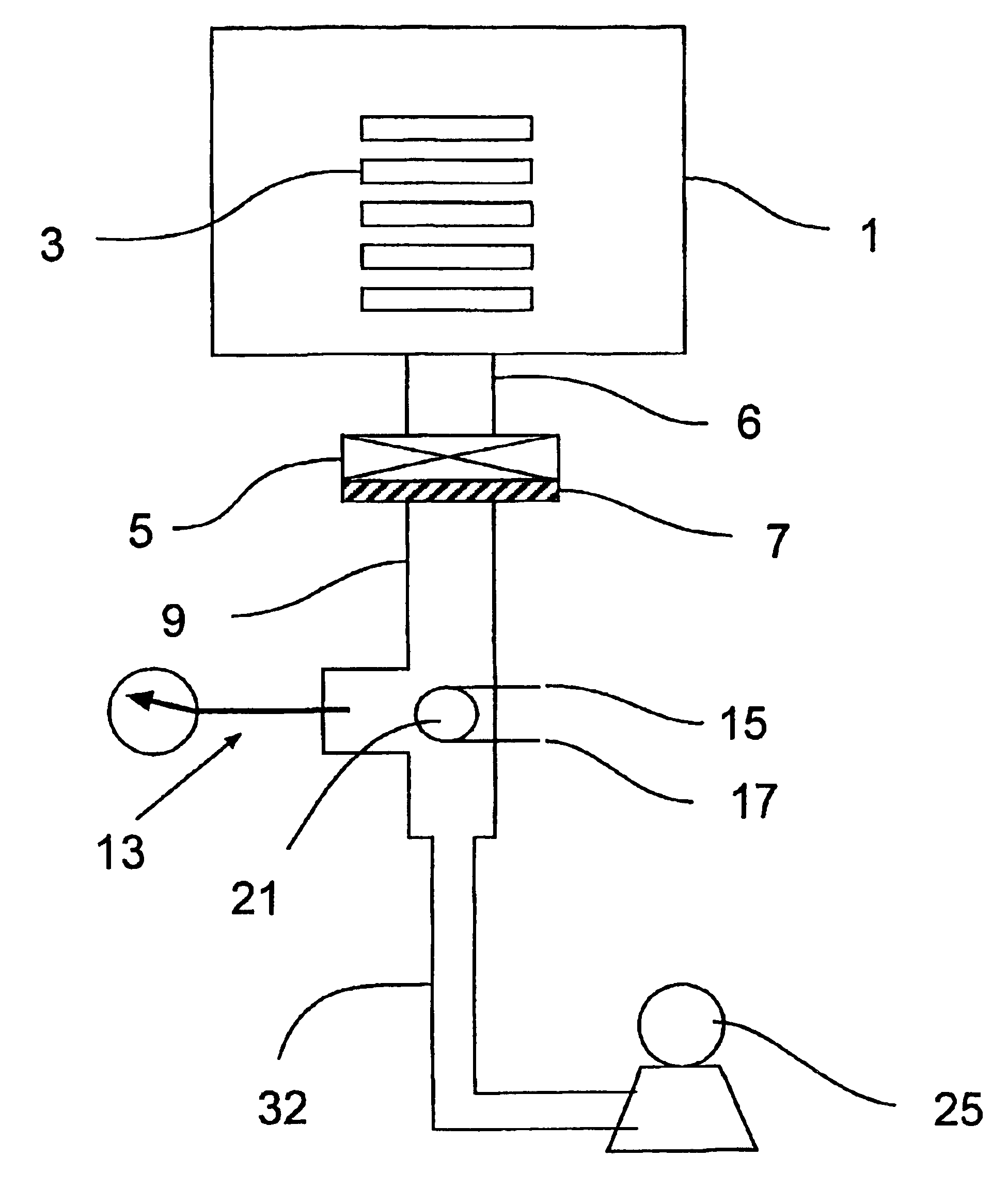
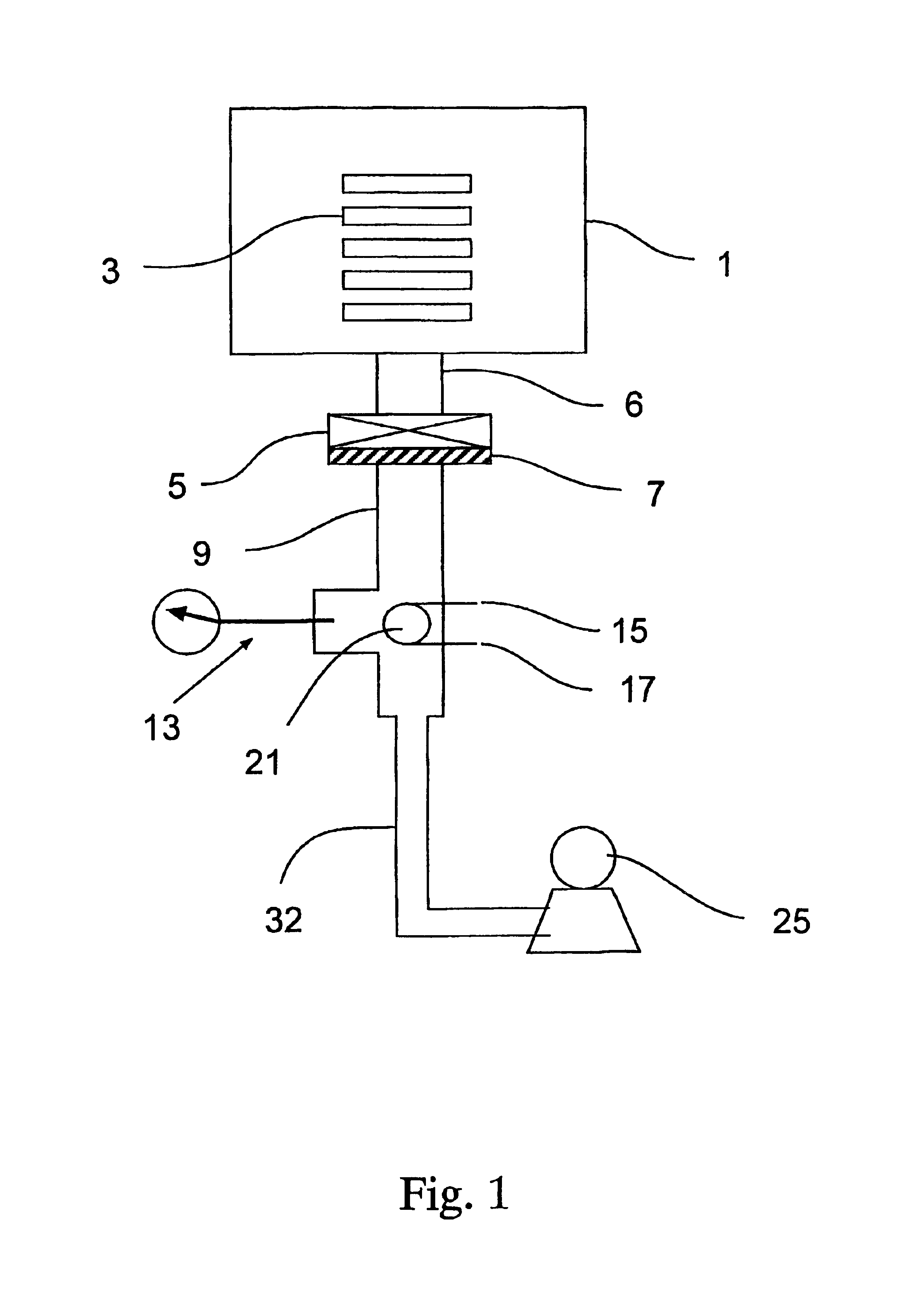
[0022]By locating the sensor in the fore-line of the vacuum system and providing for a method to determine the concentration of gas based upon the transient response of the sensor, fast and reliable measurements proportional to gas concentration can be achieved simply and at low cost. Because the pressure in the fore-line fall below the pressure of the chamber when the isolation valve is closed, the location of the gas sensor in the fore-line provides the advantage of a reference zero gas for the sensor which can be used to simplify the calibration, response, and detection of gaseous contaminants during each processing cycle.

Problems solved by technology

This is not desirable since the operation of this sensor relies upon diffusion of the contaminant gas through the chamber to the sensor for detection.
A sensor located in the chamber may not achieve a zero state after a vacuum cycle since the vacuum level and time may not have been sufficient to remove all the gases or vapors from the chamber.
Residual gas analyzers and other mass spectrometric based gas sensors could be attached to the chamber, however these devices are expensive and require highly trained and dedicated personnel for their use.
These enhancements are expensive and cumbersome for a semiconductor manufacturing environment.
Additionally the presence of a mixing apparatus in the vacuum chamber creates particles which are intolerable for modern semiconductor manufacturing processes.
Because wafers and wafer handlers are in the chamber, it is difficult to have the electromagnetic radiation transverse the entire chamber thus limiting the positioning of the sensor, the optical path length and ultimately the detection limit of the system.
Additionally, ultraviolet light sources are required for moisture detection which requires additional cost of special safety shielding to prevent operator exposure to the radiation source.
During normal operation of a vacuum chamber, the pressure sensor of the vacuum chamber does not provide an indication of an increased water load as measured by a higher than normal base pressure.
During chamber evacuation, contamination sensors mounted to or inside the chamber experience a flow of gas away from the sensor and are not capable of measuring the true contaminant gas load of the chamber and substrates as the pressure is reduced.

Method used


Image

  • Vacuum sensor
  • Vacuum sensor
  • Vacuum sensor

Examples


example 1

[0049]A test manifold, FIG. 3, was designed to illustrate the method and apparatus for the detection of moisture in a vacuum chamber. The manifold was designed to deliver prepared challenges of moisture into a vacuum chamber to simulate exposure of the chamber to atmospheric gases.

[0050]An 8 liter vessel, 90, fit with vacuum flanges was connected to isolation valve, 94, vent valve 92, and connected to a vacuum cross 96, from Varian Vacuum Corporation, Lexington, Mass. In the vacuum cross was mounted a 10 MHz aluminum quartz microbalance crystal from International Crystal, Oklahoma City, Okla. The crystal was mounted on the leads from a power vacuum feedthrough from Varian Vacuum, and connected by leads 106 and 108 to an oscillator circuit, not shown, from Millipore Corporation, Bedford, Mass. Also mounted in the vacuum cross was Pirani vacuum gauge, 98, from BOC Edwards, Murry Hill, N.J. The vacuum cross was connected to vacuum pump 102 by valve 100. The crystal was coated with a hy...


PUM

PropertyMeasurementUnit
pressuresaaaaaaaaaa
diameteraaaaaaaaaa
pressureaaaaaaaaaa

Abstract

An apparatus and method for measuring the vapor or gas content of a vacuum chamber (1) by a vapor sensor (21) located in the fore-line of a vacuum system is provide. The gas or vapor content is determined by first providing a zero condition for the sensor using the vacuum pump (25) and them referencing the sensor response to the chamber gas during the evacuation cycle.

Description

[0001]This application claims the benefit of U.S. Provisional Application No. 60 / 270,117, filed Feb. 20, 2001.FIELD OF INVENTION[0002]This invention relates in part to a method and apparatus for measuring the concentration of a gas or vapor in a vacuum chamber. More particularly, this invention relates to an apparatus and method for sensing and determining the gas or vapor concentration in a vacuum chamber during the evacuation process. The invention also relates to a method for interpreting the sensor response alone or with other sensors to determine the concentration over time of gas or vapor in the vacuum chamber.BACKGROUND[0003]Vacuum chambers are commonly used in the manufacture of semiconductor wafers. The vacuum chamber provides a controlled environment for the microelectronics circuit manufacturing in which such processes as chemical vapor deposition, aluminum sputtering, plasma etching, or plasma ashing occur. In order for these processes to take place in high yield and wit...

Claims


Application Information

Patent Timeline
Patent Type & Authority Patents(United States)
IPC IPC(8): G01N33/00G01N7/00G01N1/00G01N1/24G01N19/10G01N25/56
CPCG01N1/24G01N7/00G01N25/56G01N33/0006G01N33/0062G01N19/10
Inventor PILLION, JOHN E.
Owner BROOKS INSTRUMENT
Learn More