Phase enhanced gas-liquid absorption method

a phase enhanced and gas technology, applied in the field of gas separation, can solve the problems of reducing the mass transfer resistance, increasing the mass transfer coefficient, and hindering the release of absorbed gas from liquid solution, so as to improve the mass transfer efficiency of the system, improve efficiency, and increase the gas absorption rate significantly

Inactive Publication Date: 2005-11-29
HU LIANG
View PDF7 Cites 27 Cited by
  • Summary
  • Abstract
  • Description
  • Claims
  • Application Information

AI Technical Summary

Benefits of technology

[0009]According to this invention, the method was carried out in a closed or partially closed vessel, where a liquid carrier, an organic mixture (or organic compound), and a gas mixture containing a gas to be absorbed were introduced from an inlet. Since the organic mixture is immiscible or at least partially immiscible with the liquid carrier, the organic mixture forms a layer or small parcels between the liquid carrier and the gas mixture. The organic mixture in the reaction vessel improved mass transfer efficiency of the system and increased the absorption rate of the gas significantly. The organic mixture served as a transportation medium. The gas was finally accumulated in the liquid carrier as in a conventional gas-liquid separation system.
[0010]In one aspect, the method of the present invention could be used to remove an impurity gas from a gas mixture of interest or to collect a gas of interest from a gas mixture at improved efficiency. In another aspect, the presence of the organic layer did not hinder the regeneration of the liquid carrier or recovery of the gas because the organic layer was removed by a settler after the absorption process was completed. Yet in another aspect, the system exhibited increased gas-liquid separation efficiency, thereby reducing the costs of operation and maintenance.

Problems solved by technology

Second, it can reduce mass transfer resistance or increase mass transfer coefficient.
However, such chemical reactions may hinder the release of the absorbed gas from the liquid solution.
These compounds reduce the performance of the solvent, cause corrosion on the reaction vessel, and increase energy consumption of the system.
Slow absorption rates at an ambient temperature result in a low efficiency of carbon dioxide recovery.
Therefore, a large amount of steam is necessary to regenerate the absorbent.
This means that it is more difficult to recover carbon dioxide from the activated solution than from a solution containing no activator.

Method used


Image

  • Phase enhanced gas-liquid absorption method
  • Phase enhanced gas-liquid absorption method
  • Phase enhanced gas-liquid absorption method

Examples


example 1

An Absorption System

[0043]In this particular example of a phase enhanced gas-liquid absorption system, a stirring cell was used as a reaction vessel. The structure of the cell is shown in FIG. 3. The stirring cell was made of glass with 100 mm inner diameter and 130 mm depth. Two agitating blades, one for the liquid carrier and the other for the gas mixture, were driven by a direct-current motor. The speeds of the agitating blades were determined by a laser meter. The temperature of the reaction vessel was controlled by a water jacket (not shown).

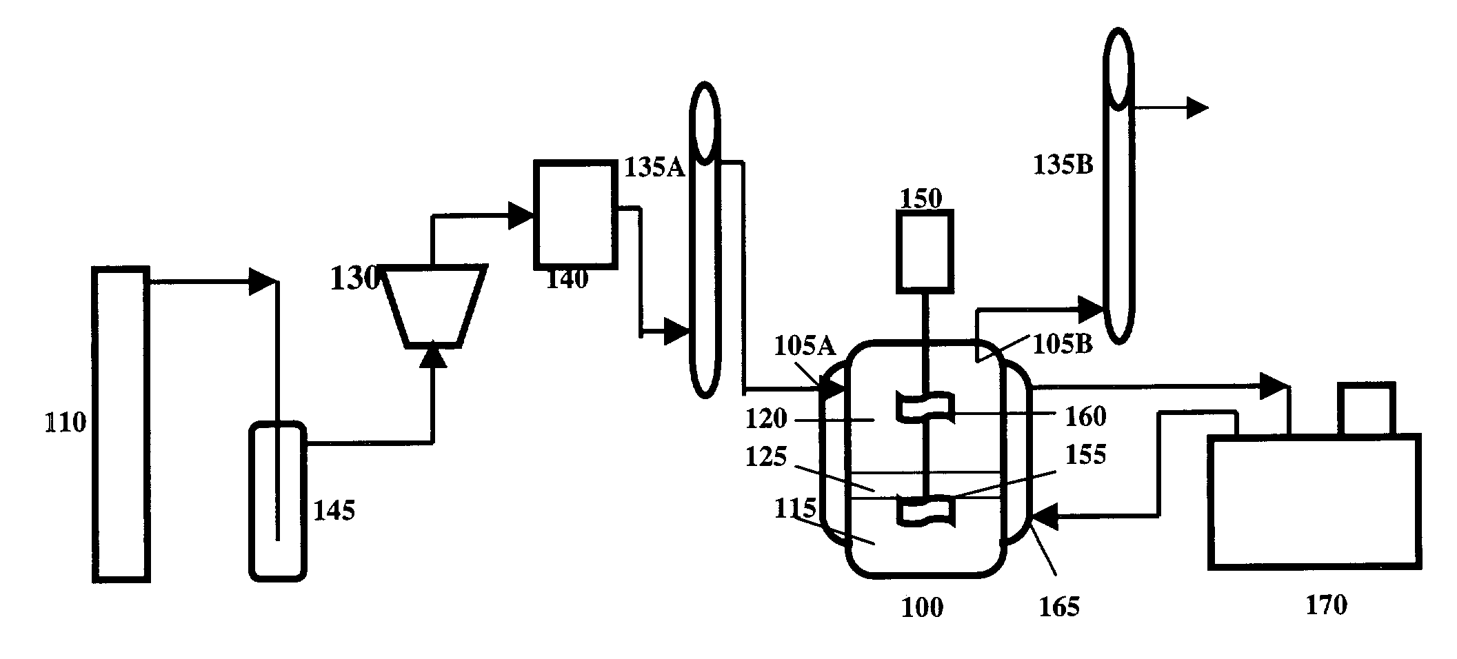
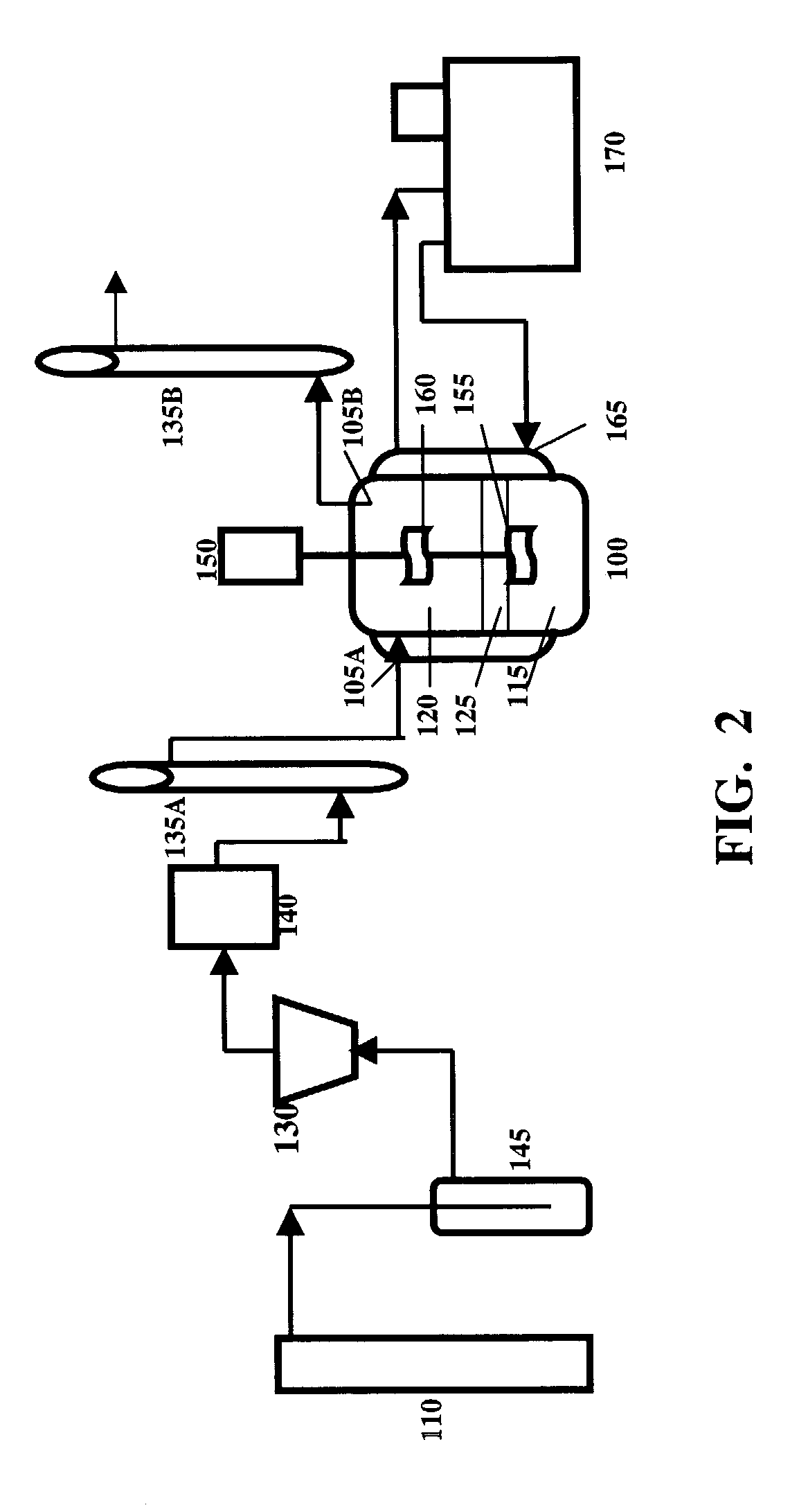
[0044]FIG. 4 is a flow chart of the system. Carbon dioxide from a cylinder 205 passed through a regulator 210, a buffer bottle 215, and a pressure stabilizing tube 220. Gas flow rate was controlled and measured by rotating flow meters 225, 230. A gas cleaning system consisted of U tubes 235, 240. The U tube 235 was filled with silicon gel while the U tube 240 contained active carbon. The gas was saturated with moisture by a bottle 243 which...

example 2

Analytical Method for Determining Absorbed Gas for the System of Example 1

[0046]The absorption rate of carbon dioxide at time t was determined by the difference of flow rates at the inlet and outlet of the reaction vessel, which were measured by the foam film flow meters 250 and 255. From the results of the measurements over a given time period, the relationship between the absorption rate r and time t was established. By integrating the absorption rate r over time t for the time period, the total amount of carbon dioxide absorbed in the liquid phase was obtained.

[0047]The concentration of carbon dioxide in the liquid carrier can be determined by using the ideal gas law. Carbon dioxide was collected upon being released from the liquid carrier by adding sulfuric acid. The mass of carbon dioxide was then computed. The mass of carbon dioxide obtained from integrating the absorption rate r over time t should be equal to the mass of carbon dioxide computed according to the ideal gas law ...

example 3

The Results of the CO2-sodium Formate Aqueous Solution Absorption System

[0048]In this example, two experiments were conducted. In the first experiment, carbon dioxide was absorbed by 280 ml sodium formate aqueous solution (400 g / l) and 20 ml organic mixture of Alamine 336 and 2-ethylhexyl alcohol (1:1 by volume). In the second experiment, carbon dioxide was absorbed by 300 ml sodium formate aqueous solution (400 g / l) directly.

[0049]In the first experiment, 280 ml sodium formate aqueous solution (400 g / L) and 20 ml liquid organic mixture were added into the reaction vessel. The liquid organic mixture, which was immiscible with the aqueous solution, formed a layer, as a second liquid phase, on top of the liquid carrier. The liquid carrier was agitated gently to facilitate the diffusion or dissolving of the gas. Agitating was sufficiently gentle so the convection moment it created did not break or destroy the layer of the liquid organic mixture. Carbon dioxide from the gas had to pass ...


PUM


Abstract

A phase enhanced gas-liquid absorption method is disclosed. By adding an organic mixture or compound into a conventional gas-liquid system, the organic mixture forms a layer between the gas mixture and the liquid carrier. In this modified system, the absorption rate of the gas is significantly increased by the organic mixture, which plays a role of transporting the gas from the gas mixture to the liquid carrier.

Description

CROSS-REFERENCE TO RELATED APPLICATIONS[0001]This patent application is a continuation-in-part application of the application Ser. No. 09 / 850,013, filed May 7, 2001, and now abandoned, titled “Method for Gas Separation by Phase Enhanced Gas-liquid Absorption, which is incorporated herein in its entirety.FIELD OF THE INVENTION[0002]This invention relates to the method for gas separation. In particular, this invention relates to a method of gas separation by phase enhanced gas-liquid absorption.BACKGROUND OF THE INVENTION[0003]Gas-liquid absorption method is still a powerful tool for separating and purifying gas. Absorbents commonly used in the liquid solution for separating carbon dioxide include alkanolamines, alkaline salt and their modified forms. To improve the performance, a chemical compound may be added to the liquid phase, which can react with the gas to form other compounds. A chemical reaction may have two beneficial effects on the absorption process. First, it can increase...

Claims


Application Information

Patent Timeline
Patent Type & Authority Patents(United States)
IPC IPC(8): B01D53/14
CPCB01D53/14
Inventor HU, LIANG
Owner HU LIANG
Why Eureka
Try Eureka