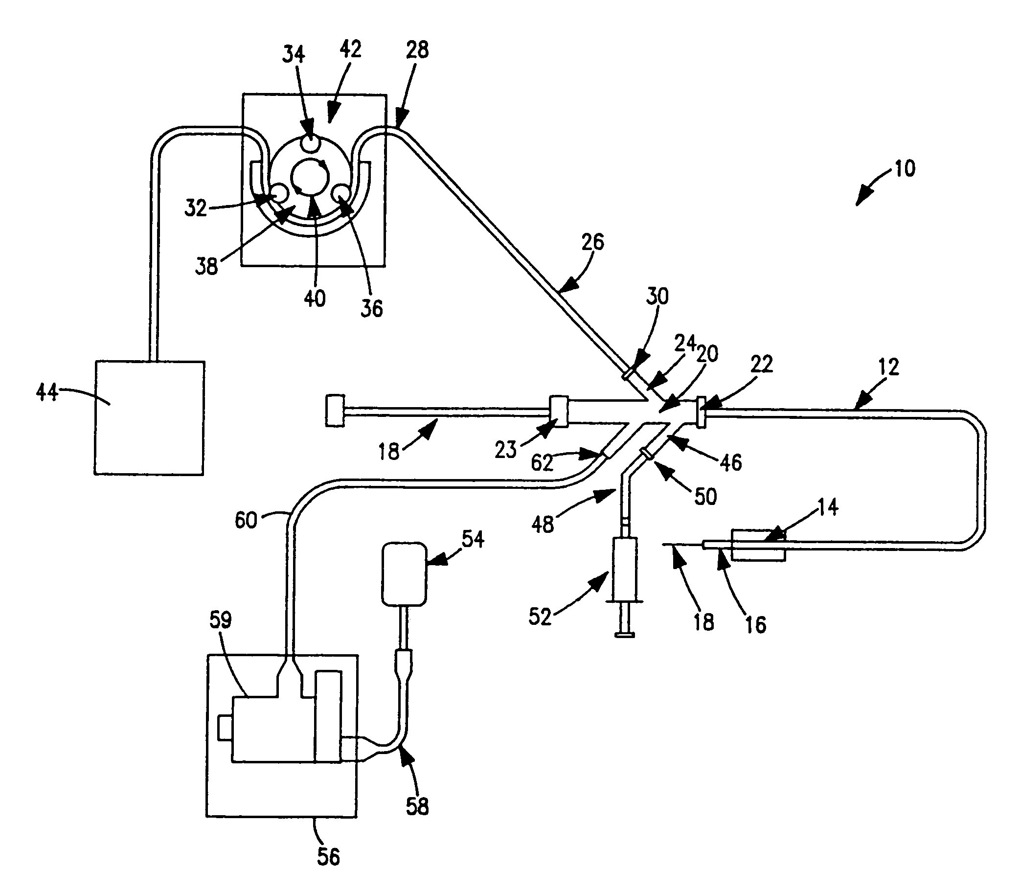
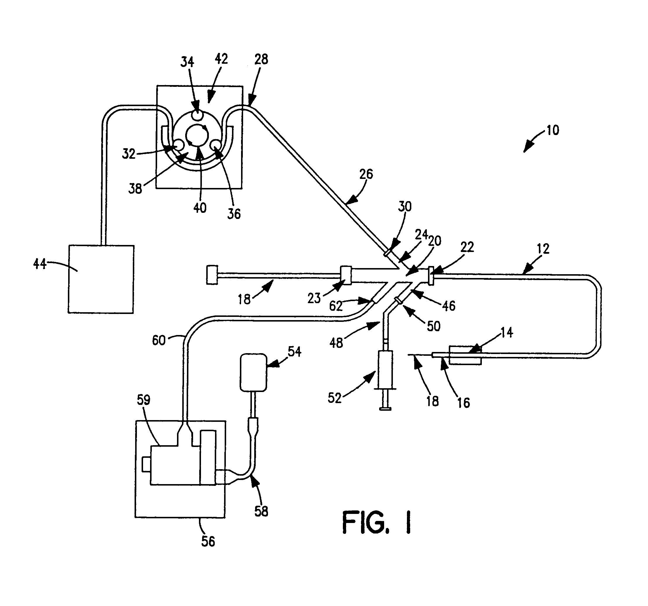
[0010]The present invention achieves the removal of unwanted tissue by utilizing high-pressure fluid jets at the distal tip of a
catheter to draw the tissue towards the catheter and
cut or emulsify the tissue; the resulting
slurry of tissue and liquid can then be removed through an exhaust lumen of the catheter, and the fluid jet(s) can provide energy to drive this exhaust. The present invention overcomes the disadvantages of the prior art systems by operating at higher pressures than those envisioned by Veltrup, thereby providing for entrainment of the thrombus or tissue into the fluid jet(s). In addition, the higher pressures produces a force which can be used to drive the fragmented tissue out of the catheter without using vacuum. The catheter can draw nearby thrombus or tissue towards the fluid jet(s), which then fragments it without requiring that the catheter be moved into direct contact or juxtaposition with the tissue. The
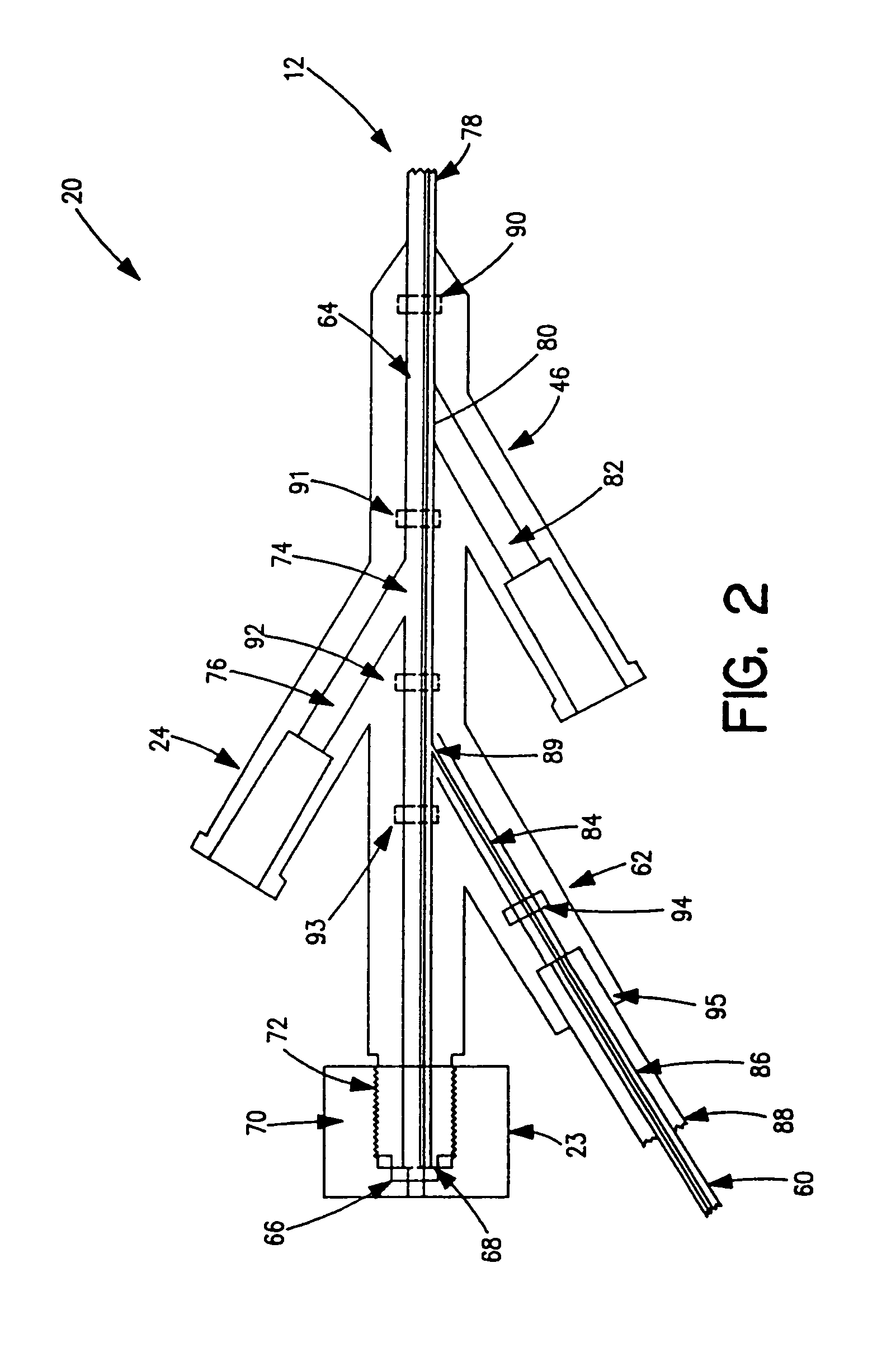
high energy of the jet impinging on the opening to the evacuation lumen eliminates the need for a
vacuum pump, as the fragmented debris is removed by the evacuation lumen as it is driven out with a driving force above atmospheric pressures.
[0011]According to the present invention, energy is added to the
system via an extremely high pressure
stream(s) of liquid, solution, suspension, or other fluid, such as saline solution, which is delivered to the distal end of the catheter via a high
pressure tubing, which directs jet(s) of
high velocity fluid at the opening of an exhaust lumen. This
stream serves to dislodge thrombus deposits, entrain them into the jet, emulsify them, and drive them out of an exhaust lumen. Tissue or debris such as thrombus particles are attracted to the jet(s) due to the localized
high velocity and
resultant localized low pressure. Recirculation patterns and fluid entrainment bring the thrombus continually into close proximity of the jet(s). Once emulsified by the jet, the tissue can be removed through the exhaust lumen by flow generated as a result of stagnation pressure which is induced at the mouth of the exhaust lumen by conversion of
kinetic energy to
potential energy (i.e., pressure) of at least one fluid jet directed at and impinging on the lumen mouth. The pressure in the high pressure fluid tubing must be great enough to generate a high localized velocity, and hence, a low localized pressure necessary to entrain the surrounding thrombus or tissue. A high enough pressure to generate substantial stagnation pressure at the opening to the exhaust lumen is necessary to drive the exhaust flow. A pressure of at least 500 psi is needed for the high pressure fluid at the tip, and pressures of over 1000 psi will provide even better entrainment and stagnation pressures. The stagnation pressure formed at the mouth of the exhaust lumen serves to drive the fragmented thrombus or tissue out of the exhaust lumen. This pressure can typically be greater than one
atmosphere, and therefore, provides a greater driving force for exhaust than can be accomplished by using a
vacuum pump. Additional jets of lower energy may be directed radially outward to aid in removal of thrombus or tissue from the vessel wall, and provide a recirculation pattern which can bring fragmented tissue into contact with the jet(s) impinging on the exhaust lumen opening.
[0012]The procedure is practiced by percutaneously or intraoperatively entering the vascular system,
tubule, or other cavity of the patient at a convenient location with a cannula. The catheter may be inserted either directly or over a previously positioned guide wire and advanced under
fluoroscopy, angioscopy or
ultrasound device to the site of the
vascular occlusion, obstruction or tissue deposit. The exhaust lumen can permit the passage of an
angioplasty dilation catheter, guidewire, angioscope, or
intravascular ultrasound catheter for intravascular viewing. The
lesion site may contain an aggregation of blood factors and cells, thrombus deposit, or other tissues which are normally identified by
angiography or other diagnostic procedure. One or more balloons may be inflated to stabilize the distal end of the catheter and provide a degree of isolation of the area to be treated. An isolation
balloon located proximal to the high pressure fluid jets can prohibit fragmented tissues from migrating proximally around the outside of the catheter shaft and immobilizing into a
side branch of a
blood vessel. An isolation
balloon distal to the high pressure fluid jets can prohibit
embolization distally. This may be of greater importance if
embolization of fragmented debris may generate unfavorable clinical sequelae. Thrombolytic drugs such as
streptokinase,
urokinase, or tPA, and other drugs may be delivered through the catheter along with the saline or separately to adjunctively aid in the treatment of the
lesion. A
balloon may also be located at the distal end of the catheter to provide the capability of dilation of the vessel, tubule, or cavity either prior to or following the thrombus or
tissue ablation and removal.

