
Capacitor compatible with high dielectric constant materials having a low contact resistance layer and the method for forming same

a capacitor and dielectric constant technology, applied in capacitors, semiconductor devices, electrical equipment, etc., can solve the problems of inability to simply deposit, inability to meet the requirements of existing processes, and physical degradation of capacitors employing former materials, so as to maximize the capacitance of storage nodes and reduce high contact resistance problems

Inactive Publication Date: 2006-03-21
NANYA
View PDF41 Cites 4 Cited by
  • Summary
  • Abstract
  • Description
  • Claims
  • Application Information

AI Technical Summary

Benefits of technology

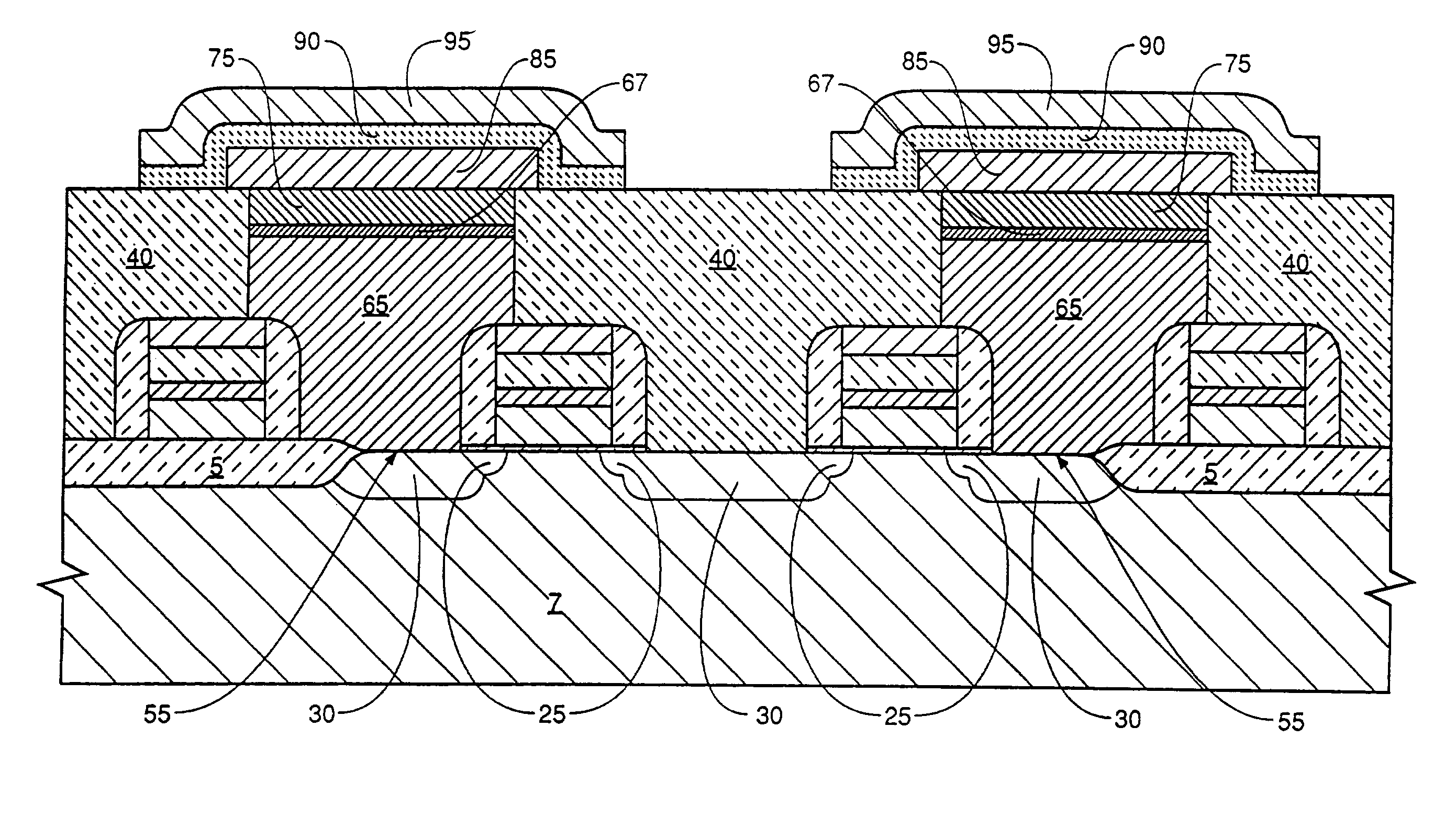
"The invention is a storage node capacitor and a method for forming it. The storage node electrode has a barrier layer that prevents the diffusion of atoms, such as titanium nitride or other materials that prevent silicon diffusion. This barrier layer is interposed between a conductive plug and a non-oxidizing conductive material, such as platinum. A dielectric layer, typically BST, is deposited on the non-oxidizing material. The barrier layer is surrounded on its sides by an insulative layer, which protects it from oxidation during the deposition and anneal of BST. This prevents oxidation of the barrier layer and the conductive plug, maximizing capacitance and reducing contact resistance. A low contact resistance material is also used between the conductive plug and the barrier layer. The method includes forming the conductive plug in a thick layer of insulative material, recessing it, and then forming the barrier layer and an oxidation resistant conductive layer in the recess. A dielectric layer is then formed to overly the storage node electrode, followed by the fabrication of a cell plate electrode. The barrier layer is protected during the formation of the dielectric layer, resulting in a maximized capacitance and reduced contact resistance."

Problems solved by technology

Unfortunately high dielectric constant materials are incompatible with existing processes and can not be simply deposited on a polysilicon electrode as was the case for the lower dielectric constant materials, such as Si3N4 and SiO2 / Si3N4 composite layers.
Also the capacitors employing the former materials undergo physical degradation during thermal cycles due to the diffusion of the cell plate material into the dielectric.
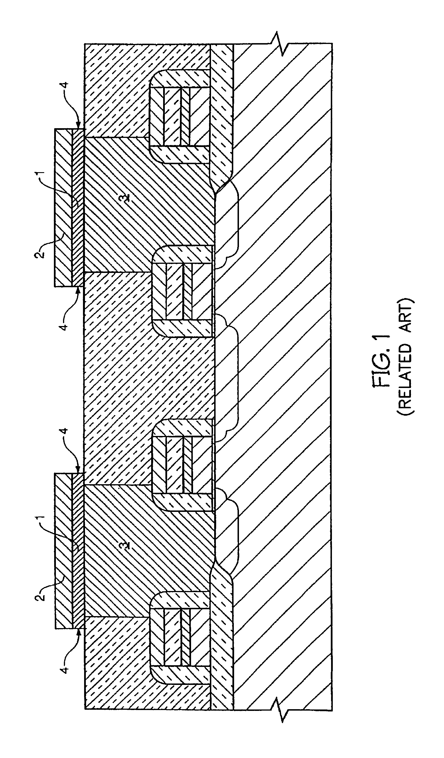
However, the sidewalls 4 of the tantalum film 1 formed during this process are subject to oxidation during the subsequent deposition of the BST layer.
Therefore the memory device cannot be made as dense.

Method used


Image

  • Capacitor compatible with high dielectric constant materials having a low contact resistance layer and the method for forming same
  • Capacitor compatible with high dielectric constant materials having a low contact resistance layer and the method for forming same
  • Capacitor compatible with high dielectric constant materials having a low contact resistance layer and the method for forming same

Examples


Embodiment Construction

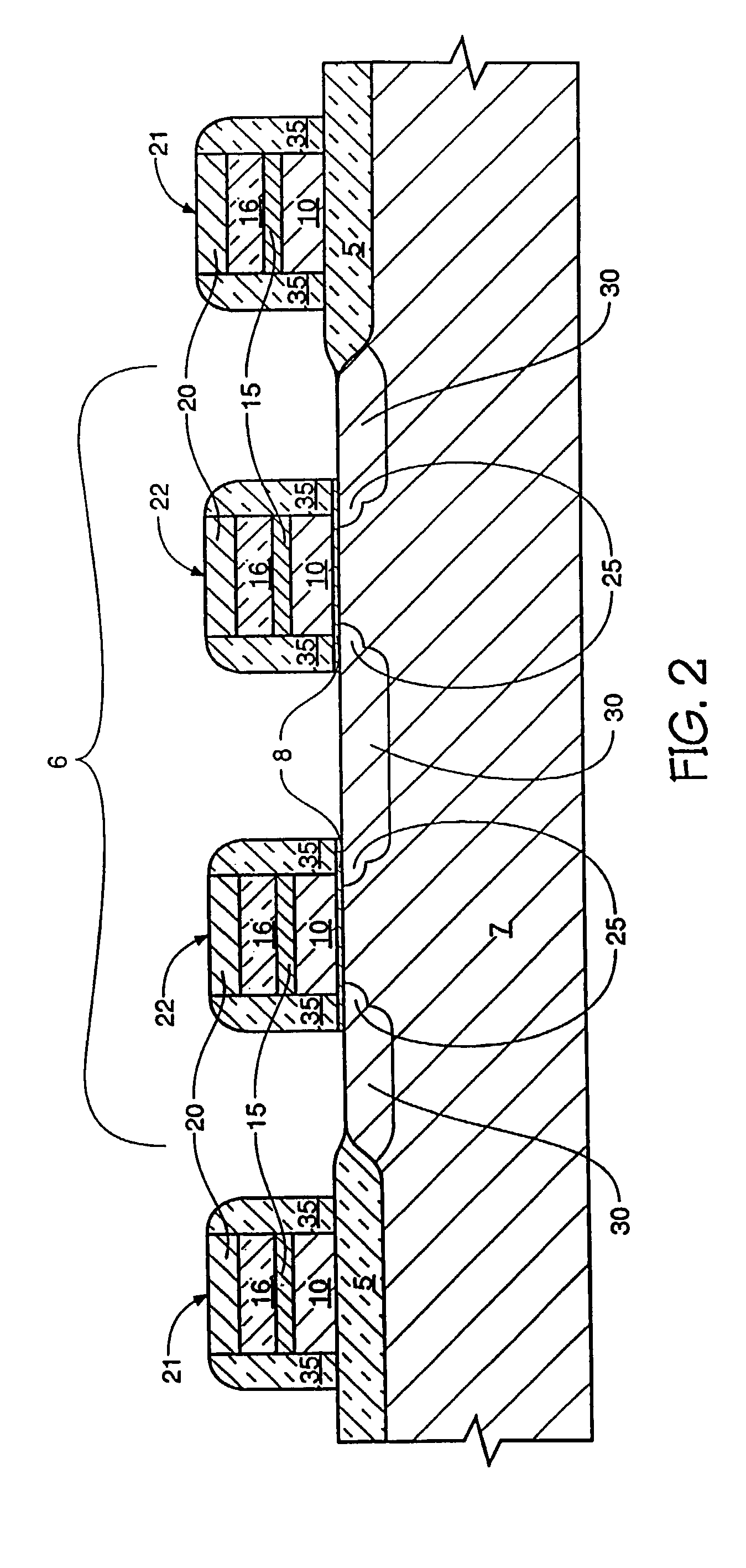
[0030]The method for fabricating the storage cell capacitor of the invention is shown pictorially in FIGS. 2–11.

[0031]Referring to FIG. 2, a cross-sectional view of an in-process dynamic random access memory (DRAM) cell is shown following conventional local oxidation of silicon (LOCOS) or special LOCOS processing which creates substantially planar field oxide regions 5 (created using modified LOCOS or trench isolation processes) and future active areas 6 (those regions of the substrate not covered by field oxide) on a silicon substrate 7. The creation of the field oxide is preceded or followed by a thermally grown dielectric layer 8 of silicon oxide. The depicted cell is one of many cells that are fabricated simultaneously and comprise a memory array. Following the creation of the field oxide region 5 and dielectric layer 8 a first conductively doped polysilicon layer 10, a metal silicide layer (Wsix) 15, an oxide layer 16, and a thick nitride layer 20 are deposited. The thick nitri...


PUM

PropertyMeasurementUnit
thicknessaaaaaaaaaa
dielectric constantaaaaaaaaaa
depthaaaaaaaaaa

Abstract

A storage cell capacitor and a method for forming the storage cell capacitor having a storage node electrode including a barrier layer interposed between a conductive plug and an oxidation resistant layer. A layer of titanium silicide is fabricated to lie between the conductive plug and the oxidation resistant layer. An insulative layer protects the sidewalls of the barrier layer during the deposition and anneal of a dielectric layer having a high dielectric constant.

Description

RELATED APPLICATIONS[0001]This application is a Divisional of U.S. Ser. No. 09 / 362,326, filed Jul. 27, 1999, now U.S. Pat. No. 6,531,730, which is a Continuation of U.S. Ser. No. 08 / 572,846, filed Dec. 14, 1995, now U.S. Pat. No. 5,959,327, which is a Continuation of U.S. Ser. No. 08 / 313,677, filed Sep. 27, 1994, now U.S. Pat. No. 5,506,166, which is a Divisional of U.S. Ser. No. 08 / 104,525, filed Aug. 10, 1993, now U.S. Pat. No. 5,381,302, which is a Continuation-In-Part of U.S. Ser. No. 08 / 044,331, filed on Apr. 2, 1993, abandoned, and is a sister application to U.S. Ser. No. 08 / 104,524, filed Aug. 10, 1993, now U.S. Pat. No. 5,392,189, all of which are incorporated herein by reference.FIELD OF THE INVENTION[0002]This invention pertains to semiconductor technology, and more particularly to storage cell capacitors for use in dynamic random access memories.BACKGROUND OF THE INVENTION[0003]As memory devices become more dense it is necessary to decrease the size of circuit components....

Claims


Application Information

Patent Timeline
Patent Type & Authority Patents(United States)
IPC IPC(8): H01L27/108H10B12/00H01L21/02H01L21/768H10B20/00H10B69/00
CPCH01L21/76846H01L21/76849H01L21/76855H01L21/7687H01L28/75H01L27/11502H01L27/11507H01L28/60H01L27/10852H01L21/76895H01L27/10855H01L28/55H10B12/033H10B12/0335H10B53/30H10B53/00
Inventor SANDHU, GURTEJ S.FAZAN, PIERRE C.
Owner NANYA
Learn More