Method and apparatus for obtaining enhanced production rate of thermal chemical reactions

a technology of thermal chemical reaction and production rate, which is applied in the direction of physical/chemical process catalysts, gas-gas reaction processes, separation processes, etc., can solve the problems of limited production rate, limited heat transfer rate, and longer residence time, and achieve enhanced production rate, enhanced heat transfer rate, and enhanced production rate

Inactive Publication Date: 2006-05-16
BATTELLE MEMORIAL INST
View PDF45 Cites 61 Cited by
  • Summary
  • Abstract
  • Description
  • Claims
  • Application Information

AI Technical Summary

Benefits of technology

[0019]The invention also includes a process for the catalytic conversion of at least one reactant in a thermal chemical reaction in which at least one reactant is passed into at least one reaction chamber that contains a catalyst that catalyzes the reaction of the at least one reactant; transferring heat to or from said at least one reaction chamber from or into said at least one heat exchanger; and obtaining at least one product from the reaction chamber; where the step of transferring heat, at steady-state, transfers at least 0.6 W of heat per cc of total reactor volume, such that, at steady state, the catalyst is maintained within a temperature range that reduces the formation of at least one undesirable chemical reaction product. Alternatively, the formation of undesirable chemical product(s) can be reduced by utilizing a contact time of less than about 0.3 seconds, thereby suppressing slow reactions that may form an undesirable chemical reaction product. Undesired chemical products can result from secondary reactions or slow parallel reactions. In the water-gas shift reaction, desirable products include carbon dioxide and water, and an undesirable product is methane. In steam reforming of a hydrocarbon, desirable products include hydrogen and carbon monoxide and / or carbon dioxide, and an undesirable product is coke.

Problems solved by technology

Limited production rates may result from longer residence time which is typically seconds to minutes in conventional thermal chemical reaction vessels.
The first is a diffusion limitation as reactants diffuse into and out of a catalyst-bearing porous pellet and the second is a heat transfer limitation which is a combination of heat transfer parameters (thermal conductivity and length) of catalyst supports and overall reactor geometry (shape, size, and distance to the external heat exchanger).

Method used


Image

  • Method and apparatus for obtaining enhanced production rate of thermal chemical reactions
  • Method and apparatus for obtaining enhanced production rate of thermal chemical reactions
  • Method and apparatus for obtaining enhanced production rate of thermal chemical reactions

Examples


example 1

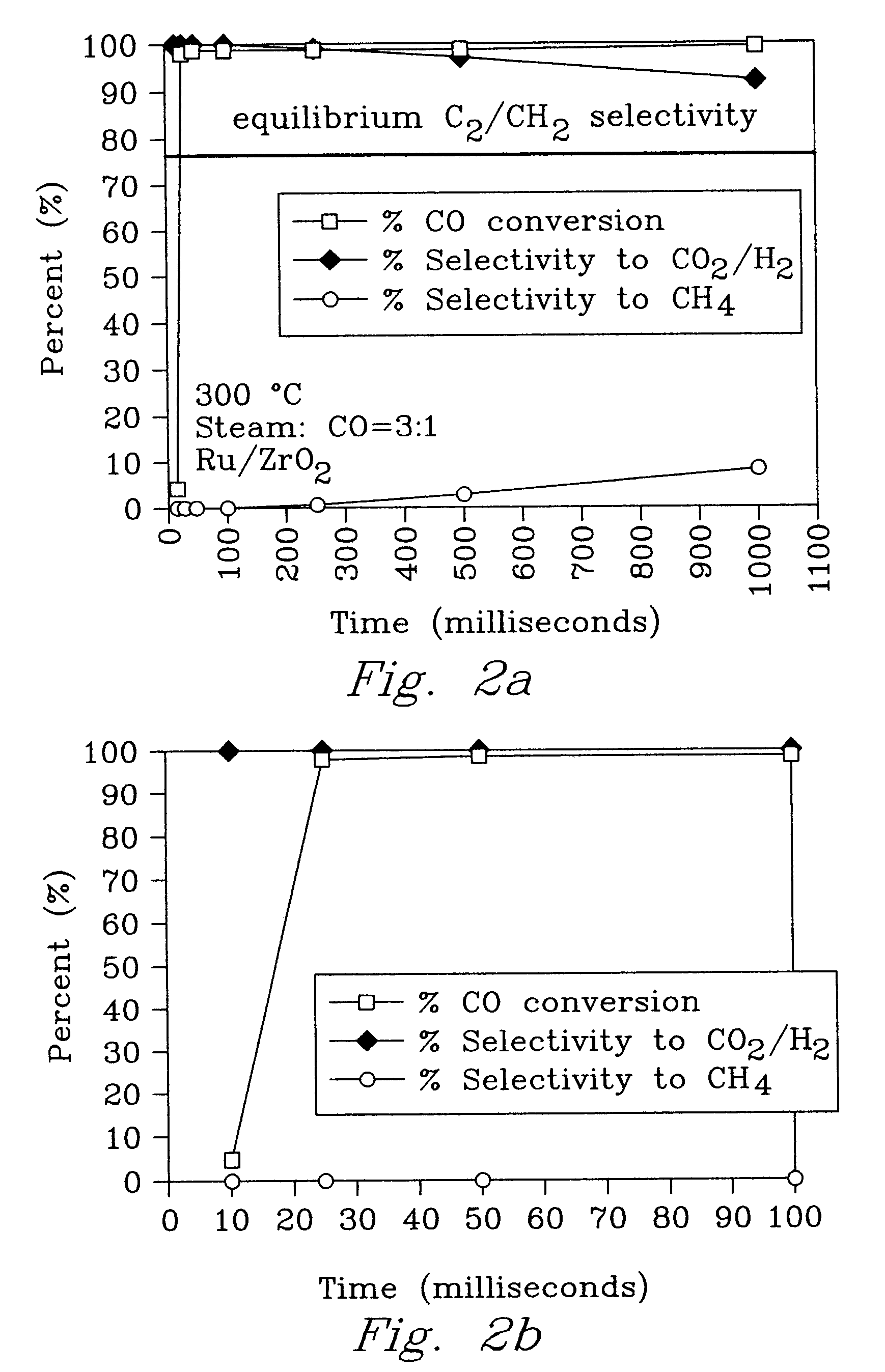
[0065]An experiment was conducted to demonstrate a chemical thermal reactor according to the present invention using the water gas shift reaction.

[0066]A first porous insert was made with a catalyst material of a pre-reduced and stabilized 5-wt % Ru / ZrO2 catalyst (⅛-inch extrudates) obtained from Degussa Corporation. The catalyst material was ground and sieved to 65 to 100 mesh.

[0067]A second porous insert was made with Ni metal foam with 80 pores per inch (ppi) machined to fit in a 7 mm ID quartz tube, ranging from 0.5 to 2.5 cm in length. The metal foam was washed in a sonicator with acetone, chloroform, and water successively over 10-minute intervals. It was also etched in a 1M HCl solution at 60° C. for 30 min. The etched metal foam was saturated with a zirconium n-propoxide / 1-propanol solution (Aldrich), followed by ambient hydrolysis with water vapor for 72 h, then calcined at 450° C. for 4 h to form the interfacial layer. The ZrO2-coated metal foam was saturated with a dilute...

example 2

[0077]An experiment was conducted to demonstrate hydrocarbon steam reforming according to the present invention.

[0078]Using the first porous insert (powder) as in Example 1, methane steam reforming was achieved with 100% conversion at 850° C. in 25 milliseconds on a 5% Rh / gamma-Al2O3 catalyst (FIG. 4). Using the second porous insert (coated metal foam) as in Example 1, with a 5% Rh / Al2O3 catalyst / interfacial layers on 80 ppi stainless steel metal foam reduced the operating temperature by 100° C. to achieve the same performance at 750° C.

[0079]No coke formation was observed during any of the millisecond residence time experiments with lower steam to methane ratios (2.5:1).

[0080]Results for other hydrocarbons are shown in Table E2-1 wherein “time” is residence time. The data on butane, gasoline and kerosene were obtained using a powder catalyst while the data on isooctane were obtained using a foam catalyst.

[0081]

TABLE E2-1Preliminary hydrocarbon reforming databased on 5% Rh / Al2O3 cat...

example 3

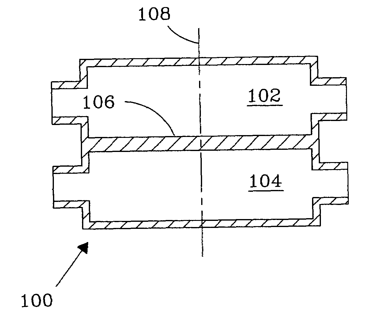
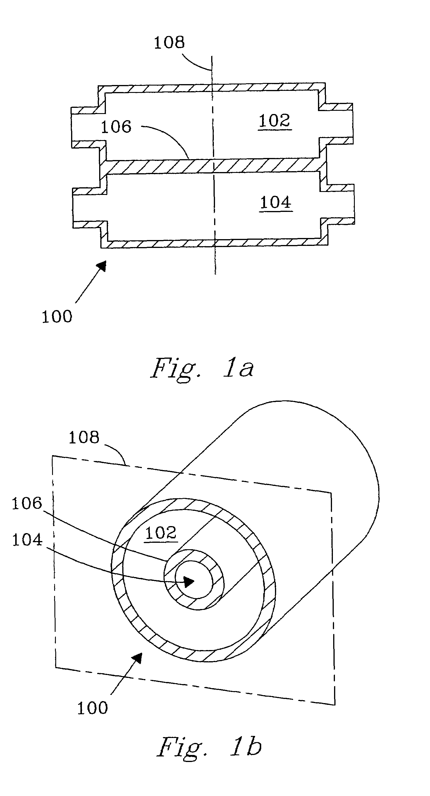
[0083]A preferred, contemplated, embodiment of the invention is shown in FIG. 6. The distance from the heat source to heat sink is about 1 centimeter or less. This distance is a function of the heat duty, the selection of heat transfer fluid(s), and the effective thermal conductivity of the porous catalyst insert. The porous catalyst insert may have a porosity greater than 95%, which creates an effective thermal conductivity roughly two orders of magnitude below the pure metal or alloy forming the porous support.

[0084]Thin sheets or tubes can be used to obtain high heat duties and short contact times. The thickness of the web between the reaction channel and the heat exchange channel can vary, but is preferably between about 0.01 inches and about 0.25 inches. The preferred thickness for the heat exchange channel preferably ranges from 100 microns to 10 millimeters. The preferred thickness is 250 microns to 3 millimeter. Flow of the heat transfer fluid may be either counter-current, ...


PUM

PropertyMeasurementUnit
heightaaaaaaaaaa
heightaaaaaaaaaa
thicknessaaaaaaaaaa

Abstract

Reactors and processes are disclosed that can utilize high heat fluxes to obtain fast, steady-state reaction rates. Porous catalysts used in conjunction with microchannel reactors to obtain high rates of heat transfer are also disclosed. Reactors and processes that utilize short contact times, high heat flux and low pressure drop are described. Improved methods of steam reforming are also provided.

Description

RELATED APPLICATIONS[0001]This application is a divisional of Ser. No. 09 / 492,246, filed Jan. 27, 2000, now U.S. Pat. No. 6,616,909, which was a continuation-in-part of U.S. Ser. No. 09 / 123,779, filed Jul. 27, 1998, now U.S. Pat. No. 6,540,975, which are incorporated by reference.[0002]This invention was made with Government support under Contract DE-AC0676RLO1830 awarded by the U.S. Department of Energy. The Government has certain rights in the invention.FIELD OF THE INVENTION[0003]The present invention relates to a method and apparatus for thermal chemical reactions. The method and apparatus can provide an enhanced reaction rates for thermal chemical reactions.BACKGROUND OF THE INVENTION[0004]Thermal chemical reactions are those chemical reactions that produce (exothermic) or consume (endothermic) heat. Examples of thermal chemical reactions include hydrocarbon conversion reactions such as steam reforming, water-gas shift reactions and combustion. These well-known reactions are us...

Claims


Application Information

Patent Timeline
Patent Type & Authority Patents(United States)
IPC IPC(8): C01B3/26B01J8/04C01B3/16C07C1/02F28D7/00B01J19/24B01J8/02B01J12/00B01J19/00B01J23/46B01J33/00C01B3/38C07B61/00
CPCB01J8/0285F28D7/00B01J12/007B01J19/0093B01J19/249C01B3/16C01B3/38C01B3/384C01B3/48B01J8/067B01J2208/00194B01J2208/00212B01J2208/00309B01J2219/00783B01J2219/00788B01J2219/00822B01J2219/00835B01J2219/0086B01J2219/00873B01J2219/00984B01J2219/2453B01J2219/2454B01J2219/2458B01J2219/2465B01J2219/2481B01J2219/2497C01B2203/0233C01B2203/0283C01B2203/0495C01B2203/066C01B2203/0811C01B2203/0833C01B2203/1005C01B2203/1023C01B2203/1029C01B2203/1041C01B2203/1047C01B2203/1058C01B2203/1064C01B2203/1082C01B2203/1241C01B2203/1247C01B2203/1288C01B2203/1619C01B2203/1633C01B2203/1652C01B2203/1676C01B2203/169Y02P20/52
Inventor TONKOVICH, ANNA LEE Y.WANG, YONGWEGENG, ROBERT S.GAO, YUFEI
Owner BATTELLE MEMORIAL INST
Why Eureka
Try Eureka