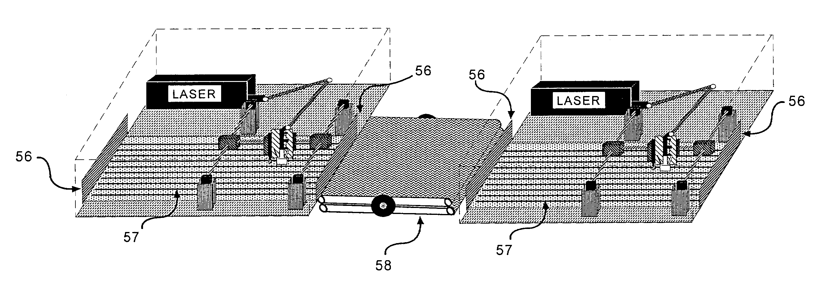
Al technical title is built by PatSnap Al team. It summarizes the technical point description of the patent document.
a laser drilling and conveying technology, applied in the field of conveying blind microvia laser drilling system, can solve the problem of ineffective manufacture of vacuum hold down, achieve the effect of improving the peak power of the laser beam, “cleanly” removing material, and high speed ra
Inactive Publication Date: 2006-06-20
MARGER JOHNSON & MCCOLLOM P C
View PDF32 Cites 27 Cited by
Summary
Abstract
Description
Claims
Application Information
AI Technical Summary
This helps you quickly interpret patents by identifying the three key elements:
Problems solved by technology
Method used
Benefits of technology
[0023]The marriage of several physical components for this invention are not obvious since the natural tendency is to work up the laser beam with more and shorter pulses which improves the peak power of the laser beam, but unfortunately also forces the beam to be precisely oriented over the pre-etched window for a period of time sufficient to accomplish the removal of the dielectric material. This invention is a true drill-on-the-fly method, as the laser beam is “dragged” over the pre-etched window. A long focal length beam lens allows the beam to penetrate deeply into the dielectric material and “cleanly” remove material with a single pulse. One of the most counter-intuitive characteristics of the method described in this invention is the ultra-clean surfaces of copper on the second level and at the bounce pad at the base of the blind microvia, where the laser beam is reflected from these surfaces 14 with a single pulse (as shown in FIGS. 7, 9, 11, and 13). The single pulse does not create charring, because th...
Problems solved by technology
For this reason it would be impossible to effectively manufacture a vacuum hol...
Method used
Image
Click on the blue label to locate the original text in one second.
Reading with bidirectional positioning of images and text.
Examples
Embodiment Construction
Overview of System and Process
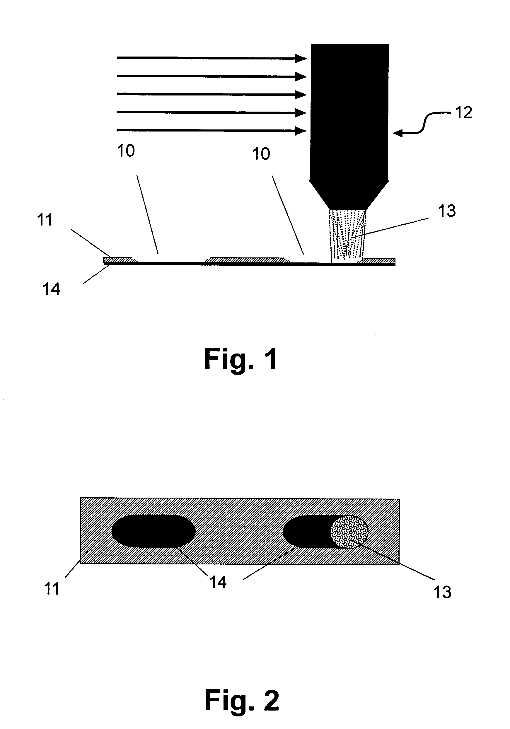
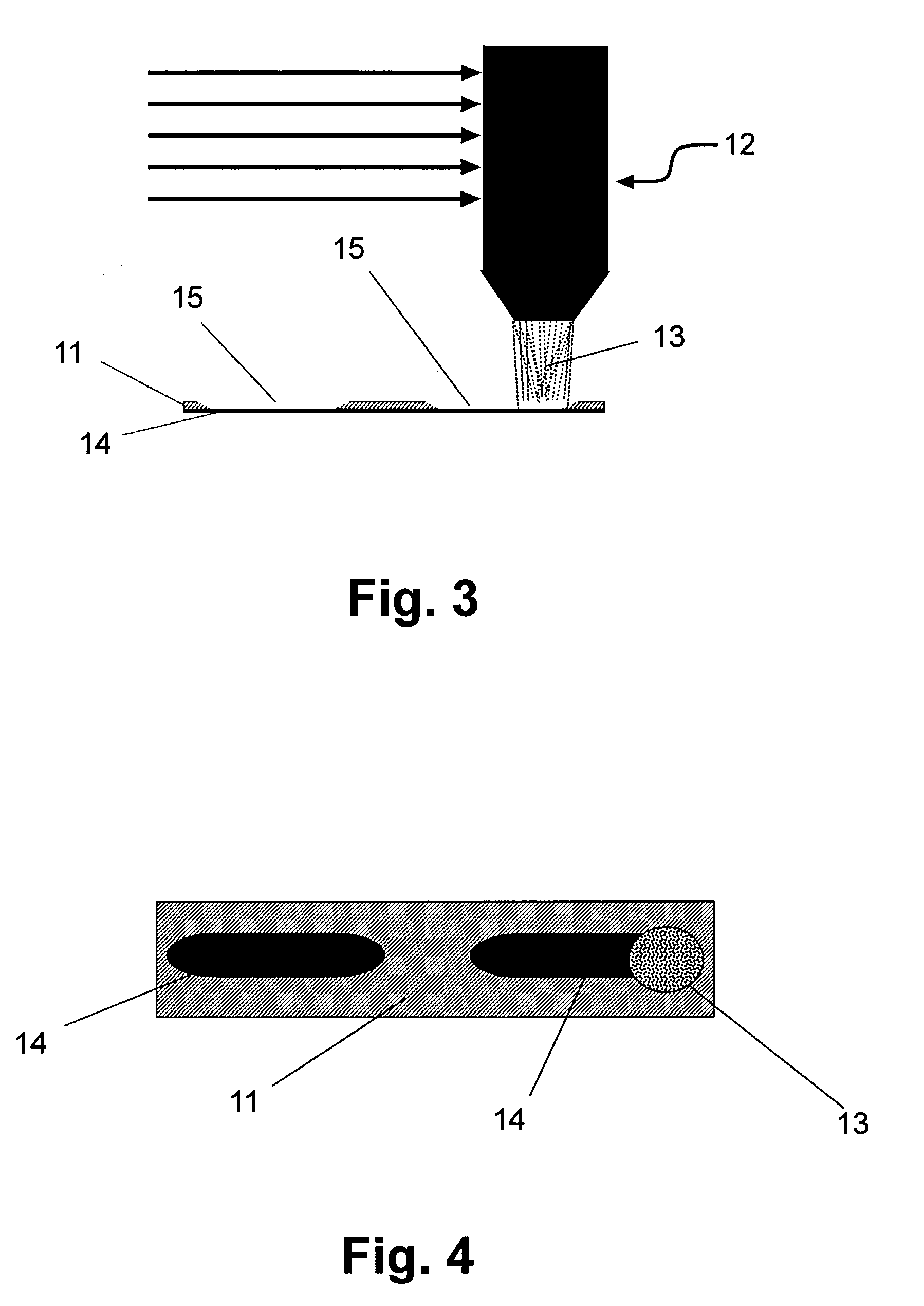
[0064]In accordance with a preferred embodiment of the present invention, a laser system is constructed by integrating a sufficiently powerful (preferably >240 watts, more preferably 500 watts) sealed carbon dioxide (CO2) laser emitting an infrared (10.6 micrometer) laser beam pulsed by using radio frequency controls (RF excited). Synrad, Inc. (Mukilteo, Wash., U.S.A.), Rofin Sinar (Hamburg, Germany) and Coherent, Inc., (Santa Clara, Calif., U.S.A.) make lasers that can be adapted to perform as described herein. The 10.6-micrometer frequency of the laser beam is important so that the natural reflective properties can be utilized where the beam is not absorbed by the copper clad of the circuit board conformal coat, allowing the copper clad thickness to be very thin. Since the process of removing dielectric material is a photo-therm process, heat is involved and must be controlled to the extent possible. The other material contributing to the success of t...
PUM
Property
Measurement
Unit
Mass
aaaaa
aaaaa
Speed
aaaaa
aaaaa
Electrical conductor
aaaaa
aaaaa
Abstract
A laser drilling system for drilling blind vias in printed circuit board panels, multichip modules and chipscale packages with top and bottom surfaces and which include multiple dielectric polymer and metal layers. The system includes a first laser module comprising a laser able to form at least one via per pulse through one or more polymer layers. The vias are circular or non-circular in shape. An articulated arm is adapted to move at a speed of about 200 inches per second and at an acceleration of about 5 g's or more. A beam delivery unit is attached to the articulated arm and a conveyor adapted to move panels at a constant speed. The first laser module positioned on a separate track from the conveyor moves at a faster rate than the conveyor to drill the top surface. A second laser module is positioned to move on another separate track from the conveyor movable at a faster rate so as to drill the bottom surface.
Description
RELATED APPLICATION DATA[0001]This application claims benefit to Provisional application U.S. Ser. No. 60 / 366,484 filed on Mar. 20, 2002 and is a continuation-in-part of U.S. Ser. No. 09 / 823,217 filed Mar. 30, 2001, now U.S. Pat. No. 6,634,558 which is a continuation-in-part of U.S. Ser. No. 09 / 194,933, filed Dec. 4, 1998, now U.S. Pat. No. 6,211,485, which is a continuation in part PCT / US97 / 09732, filed Jun. 5, 1997, and from U.S. Ser. No. 60 / 019,140, filed Jun. 5, 1996, all commonly owned and incorporated herein by reference.BACKGROUND OF THE INVENTION[0002]The present invention relates to a laser system and method of forming production volumes of economical and reliable blind vias in circuit boards, polymer based multichip modules and chipscale packages at speeds estimated to exceed 2,000 per second.[0003]Laser drilled blind vias are constructed by passing and pulsing laser beam radiation over a pre etched window to remove dielectric material. The use of pre etched windows as a m...
Claims
Application Information
Patent Timeline
Application Date:The date an application was filed.
Publication Date:The date a patent or application was officially published.
First Publication Date:The earliest publication date of a patent with the same application number.
Issue Date:Publication date of the patent grant document.
PCT Entry Date:The Entry date of PCT National Phase.
Estimated Expiry Date:The statutory expiry date of a patent right according to the Patent Law, and it is the longest term of protection that the patent right can achieve without the termination of the patent right due to other reasons(Term extension factor has been taken into account ).
Invalid Date:Actual expiry date is based on effective date or publication date of legal transaction data of invalid patent.