Electromechanical actuators

a technology of electromechanical actuators and actuators, applied in the direction of non-mechanical valves, device material selection, lighting support devices, etc., can solve the problems of lead toxicity and associated difficulties in processing, crystal growth and handling, and high density and relatively low elastic modulus of lead based perovskites, and achieve superior electromechanical properties and improved strain coefficients. , the effect of low lead or lead-fr

Inactive Publication Date: 2006-08-15
MASSACHUSETTS INST OF TECH
View PDF28 Cites 93 Cited by
  • Summary
  • Abstract
  • Description
  • Claims
  • Application Information

AI Technical Summary

Benefits of technology

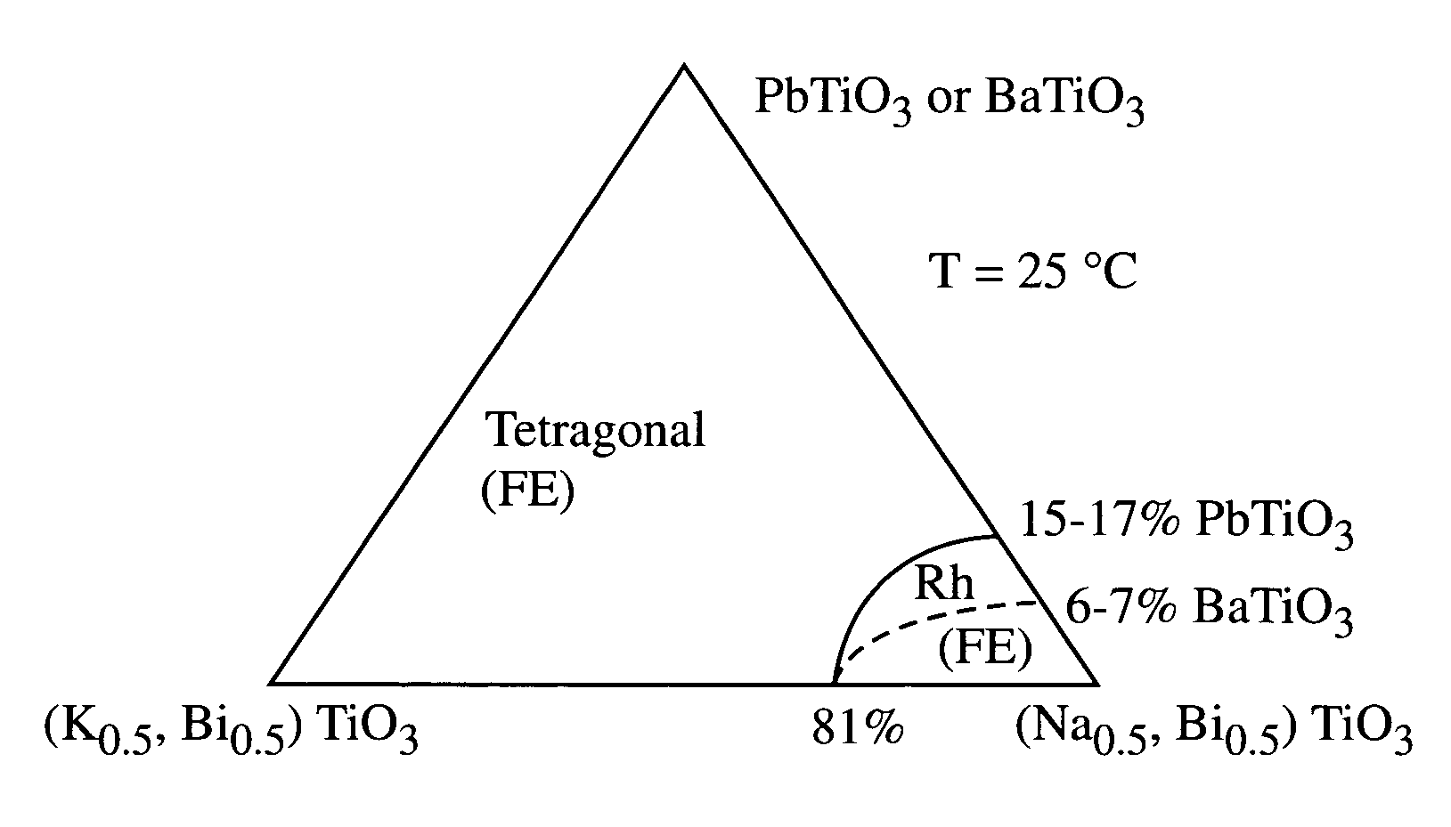
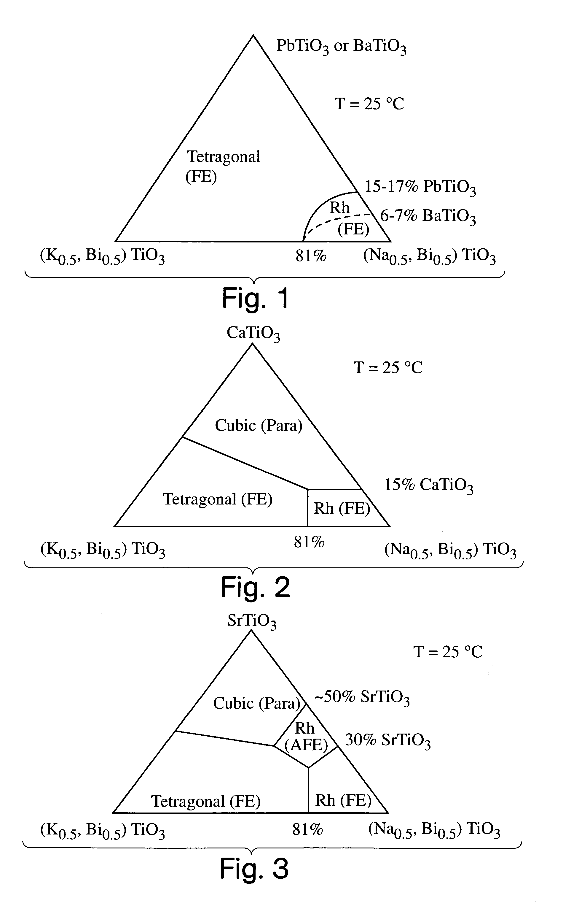
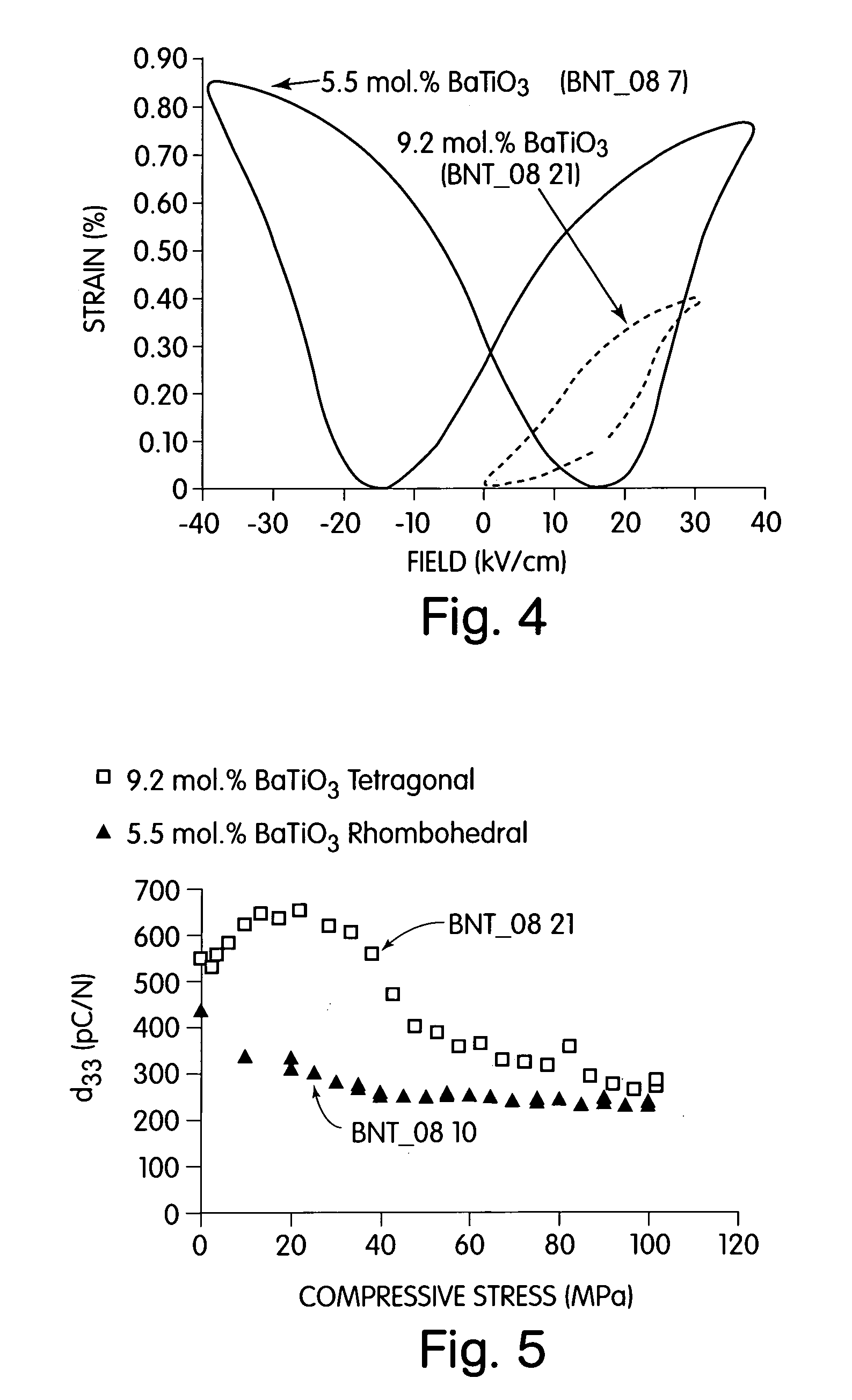
[0029]Increased doping of BaTiO3 beyond the 6% BT-MPB composition in NBT-BT continues to stabilize the ferroelectric tetragonal phase. This invention demonstrates that through simultaneous doping on the A- and B-sites in NBT with Ba2+ and Zr4+, respectively, rhombohedral and tetragonal non-ferroelectric phases can be stabilized for higher concentrations of Ba2+ (up to 26 mol % Ba2+). Within the same phases, relaxor properties are often enhanced by the introduction of greater Ba2+ doping.

Problems solved by technology

A drawback to all these lead-based perovskites is the toxicity of lead and associated difficulties in processing, crystal growth and handling.
In certain environmentally sensitive or biologically sensitive applications, they can not be used.
Another drawback is the high density and relatively low elastic modulus of the lead based perovskites.
While the intrinsic electromechanical properties of properly oriented single crystals appear to be attractive, there are numerous obstacles to their practical implementation.
Firstly, the growth, orientation, cutting and handling of large single crystals is expensive and difficult.
Secondly, ceramic ferroelectrics are mechanically brittle and weak, more so than other ceramics such as aluminum oxide, silicon nitride or silicon carbide.
Nonetheless, a conventional polycrystalline ferroelectric, electrostrictive or magnetostrictive actuator suffers in performance relative to an optimally oriented single crystal.
However, it is well-known to those skilled in the art that polycrystalline ceramics are difficult to prepare in a textured form.
While oriented polycrystalline perovskite ferroelectrics have been accomplished in the form of thin films supported by a substrate they have not been achieved in polycrystals suitable for actuation devices.

Method used


Image

  • Electromechanical actuators
  • Electromechanical actuators
  • Electromechanical actuators

Examples


example 1

Single Crystal Growth in the System Na(1 / 2)Bi(1 / 2)TiO3—BaTiO3

[0159]A powder mixture of the target composition (0.94)Na(1 / 2)Bi(1 / 2)TiO3-(0.06)BaTiO3 was prepared, with wt % each of Na2CO3 and Bi2O3 being added in excess in order to form a liquid flux. The powder mixture was prepared from the following starting materials in the following amount

[0160]

CompoundManufacturerAmount (g)CommentBi2O3Morton Thiokol102.340820 wt % excess of thecomponentNa2CO3MCB Reaoents23.276420 wt % excess of thecomponentTiO3NanoTek58.4750BaTiO3Morton Thiokol10.8980

The powders were ball-milled in a 1000 mL polypropylene bottle containing 50% by volume of zirconia milling media and ˜350 mL ethanol for ˜12 hours at a rolling speed of 120 rpm. The mixed powder was dried with a heating lamp, then ground in a mortar and pestle, then placed in an alumina crucible (100 mL) with a cover and calcined in air according to the following heating schedule: 8 hour ramp from room temperature to 800° C., hold for 2 hours, fur...

example 2

Single Crystal Growth in the System Na(1 / 2)Bi(1 / 2)TiO3—K(1 / 2)TiO3—BaTiO3

[0176]The nominal crystal composition of this batch was (0.782)Na(1 / 2)Bi(1 / 2)TiO3-(0.138)K(1 / 2)Bi(1 / 2)TiO3-(0.08)BaTiO3. A greater amount of excess Bi2O3 and Na2CO3 was added in this growth run than in Example 1. The amounts of each component are given in the table below:

[0177]

CompoundManufacturerAmount (g)CommentsBi2O3Alfa Aesar73.7132includes 20 wt % of totalNa2CO3Alfa Aesar31.2103includes 20 wt % of totalTiO2Nanotek39.2722K2CO3Alfa Aesar2.3442BaCO3Alfa Aesar0.6209

[0178]The processing conditions were similar to those used for Example 1. A Thermolyne Hi-temp, model 46100 furnace was used. The crystal growth schedule was as follows: 13.5 hour ramp from room temperature to 1350° C., hold for 5 hours, cool slowly at a rate of 5° C. / min to 800° C., then furnace-cool to room temperature. The growth run yielded smaller crystals of cubic habit and approximately 1 mm dimension in a larger amount of crystallized flux. ...

example 3

Textured Crystallites by Cleavage and Capillary Aggregation

[0181]Several of the Ba-doped NBT crystals of Example 1 were ground coarsely using a mortar and pestle. The resulting powder was mixed with the liquid binder collodion, and spread on a glass slide. The slide was heated for about 10 minutes in a small box furnace to set the glue. During drying, the powder tends to settle against the glass surface, and the capillary action of the liquid also helps to draw the particles together and against the glass surface. After drying, the powder was subjected to powder x-ray diffraction. The x-ray diffraction pattern, FIG. 15, shows stronger intensity for the (202) reflection of the rhombohedral phase ((200) of the corresponding cubic phase) than does a randomly oriented powder. In the powder diffraction pattern for NBT, JCPDS, file 36-0340, the (110) of the rhombohedral phase is expected to have the highest intensity. In our sample, the (202) has the highest intensity, showing that prefer...


PUM

PropertyMeasurementUnit
electric fieldaaaaaaaaaa
temperatureaaaaaaaaaa
Curie temperatureaaaaaaaaaa

Abstract

A perovskite compound of the formula, (Na1 / 2Bi1 / 2)1-xMx(Ti1-yM′y)O3±z, where M is one or more of Ca, Sr, Ba, Pb, Y, La, Pr, Nd, Sm, Eu, Gd, Th, Dy, Ho, Er, Tm, Yb and Lu; and M′ is one or more of Zr, Hf, Sn, Ge, Mg, Zn, Al, Sc, Ga, Nb, Mo, Sb, Ta, W, Cr, Mn, Fe, Co and Ni, and 0.01<x<0.3, and 0.01<y<0.3, and z<0.1 functions as an electromechanically active material. The material may possess electrostrictive or piezoelectric characteristics.

Description

[0001]This application is a continuation of U.S. patent application Ser. No. 09 / 827,806, filed Apr. 6, 2001, entitled “Electromechanical Actuators,” now abandoned, which is a continuation-in-part application of U.S. patent application Ser. No. 09 / 174,981 filed Oct. 19, 1998, entitled “Piezoelectric Actuators and Methods of Making Same,” now U.S. Pat. No. 6,231,779, which is incorporated herein by reference.[0002]U.S. patent application Ser. No. 09 / 174,981 also claims the benefit of U.S. Provisional Patent Application Ser. No. 60 / 085,109, filed May 12, 1998 and U.S. Provisional Patent Application Ser. No. 60 / 062,531, filed Oct. 20, 1997.[0003]U.S. patent application Ser. No. 09 / 827,806 also claims priority from U.S. Patent Application Ser. No. 60 / 195,835 filed Apr. 11, 2000, entitled “Electromechanical Actuators and Methods of Making Same,” incorporated herein by reference, and U.S. Patent Application Ser. No. 60 / 221,278, filed Jul. 27, 2000, entitled “Barium and Zirconium Co-Doped S...

Claims


Application Information

Patent Timeline
Patent Type & Authority Patents(United States)
IPC IPC(8): C04B35/49C04B35/00C30B9/00F01L9/20F21V21/35H01L41/18H01L41/187
CPCC01G23/006C01G29/006C01G43/006C01G49/009C01G51/006C01G53/006C04B35/462C04B35/475C04B35/49C04B35/499C04B35/62259C04B35/6261C04B35/6262C04B35/62675C04B35/62695C04B35/653C30B9/00F01L9/04F21V21/35H01L41/18H01L41/187C30B29/32C01P2002/34C01P2002/52C01P2002/72C01P2004/03C01P2004/80C01P2006/40C04B2235/32C04B2235/3201C04B2235/3206C04B2235/3208C04B2235/3213C04B2235/3215C04B2235/3217C04B2235/3224C04B2235/3225C04B2235/3229C04B2235/3234C04B2235/3236C04B2235/3241C04B2235/3244C04B2235/3251C04B2235/3256C04B2235/3258C04B2235/3262C04B2235/3272C04B2235/3275C04B2235/3279C04B2235/3284C04B2235/3286C04B2235/3287C04B2235/3293C04B2235/3294C04B2235/3296C04B2235/3298C04B2235/526C04B2235/5264C04B2235/5276C04B2235/604C04B2235/6562C04B2235/6565C04B2235/76C04B2235/762C04B2235/765C04B2235/768C04B2235/77F01L9/20H10N30/853
Inventor CHIANG, YET-MINGSHEETS, SOSSITY A.FARREY, GREGORY W.HAGOOD, IV, NESBITT W.SOUKHOJAK, ANDREYWANG, HAIFENG
Owner MASSACHUSETTS INST OF TECH
Why Eureka
Try Eureka