Laser array for generating stable multi-wavelength laser outputs

a multi-wavelength laser and laser array technology, applied in the field of optical networks, can solve the problems of high cost of making such laser arrays, inability to provide all those features, and complex channel tuning mechanisms of current mwl arrays, so as to improve the line shape of reflection spectra, improve the stability of local refractive index in any sectional position of the device, and improve the effect of thermal stability

Inactive Publication Date: 2006-09-12
LIU ZHONGSHAN
View PDF19 Cites 12 Cited by
  • Summary
  • Abstract
  • Description
  • Claims
  • Application Information

AI Technical Summary

Benefits of technology

[0024]All layers of the wavelength selectable optical device can be made of dielectric materials such as SiO2, Si3N4, HfO2, Al2O3, and TiO2 or semiconductor materials such as Si, InP, GaAs, AlGaAs, and InGaAsP. To improve the line shapes of its reflection spectra, the wavelength selectable optical device may further include any or all of the following three components: a dielectric thin-film layer on the outer surface of the grating layer, a dielectric thin-film layer between the grating layer and the waveguide layer, and a dielectric layer between the waveguide layer and the substrate.
[0025]The wavelength selectable optical device disclosed in the present invention is a passive element. No injection current flows through it. Thus, the local refractive indices in any sectional positions of the device are stable. Since the output wavelengths depend u

Problems solved by technology

No existing MWL provides all those features largely because of the limitations in current laser technologies.
One of unsolved problems with DFB or DBR MWLs is uneven wavelength drifting that can cause cross talks.
The channel tuning mechanisms of current MWL arrays are very complex.
Also, the cos

Method used


Image

  • Laser array for generating stable multi-wavelength laser outputs
  • Laser array for generating stable multi-wavelength laser outputs
  • Laser array for generating stable multi-wavelength laser outputs

Examples


second embodiment

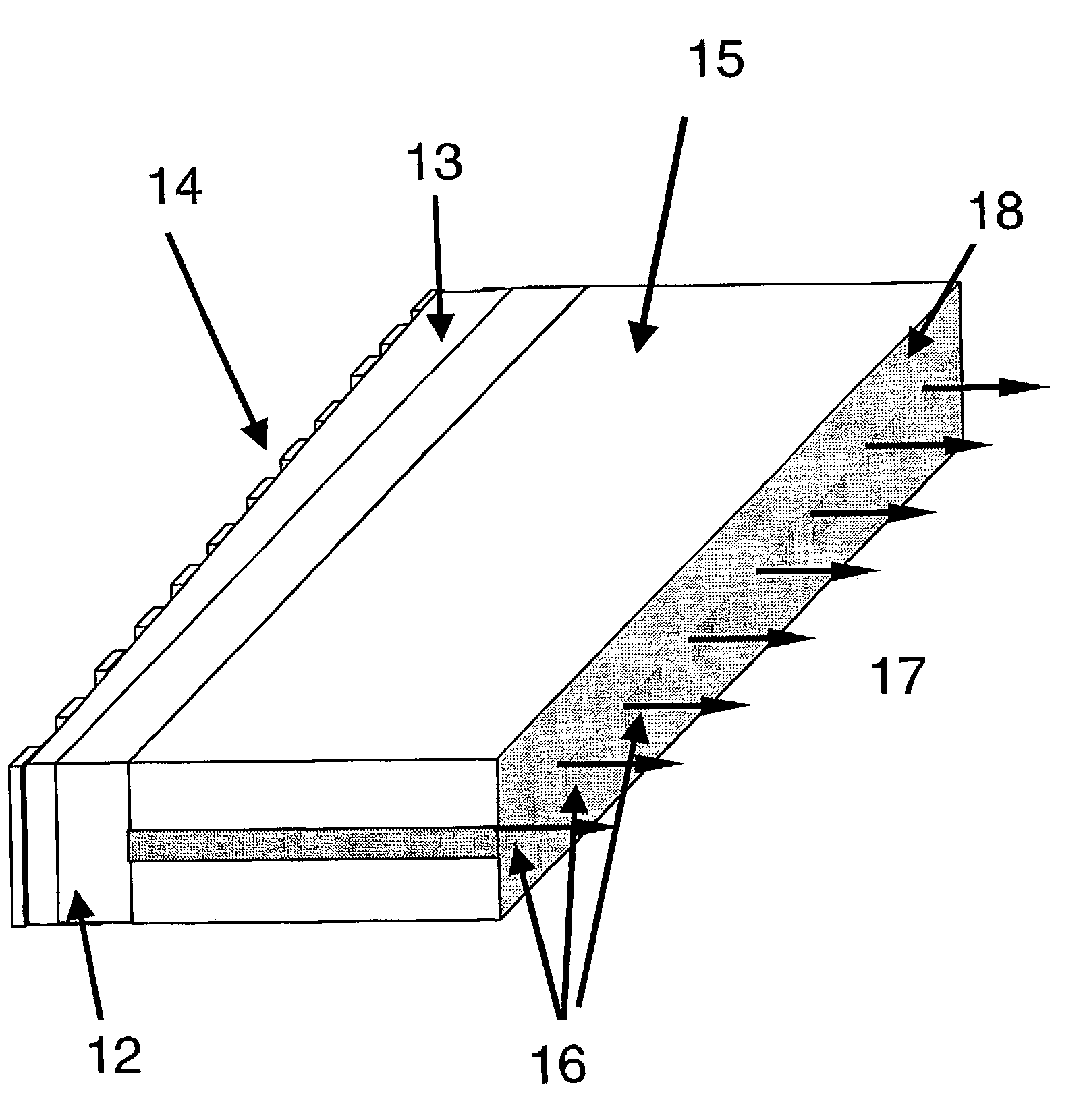
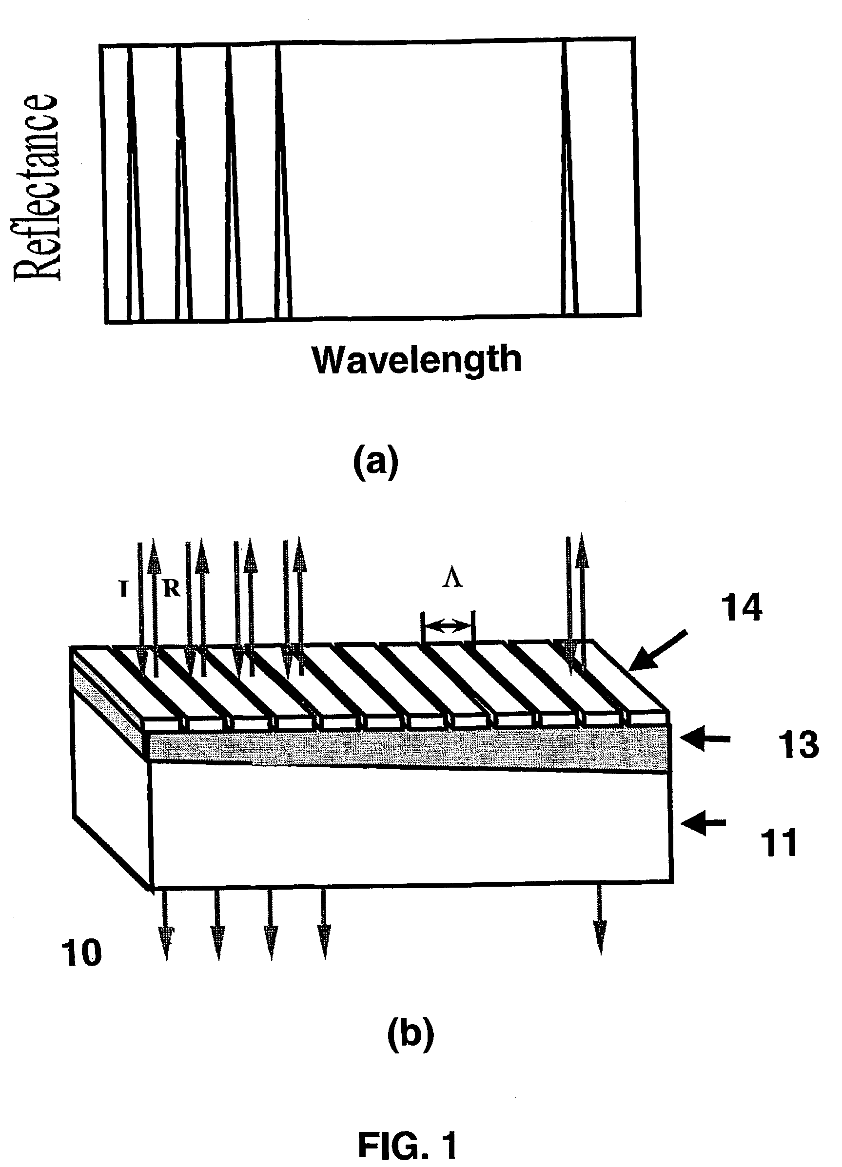
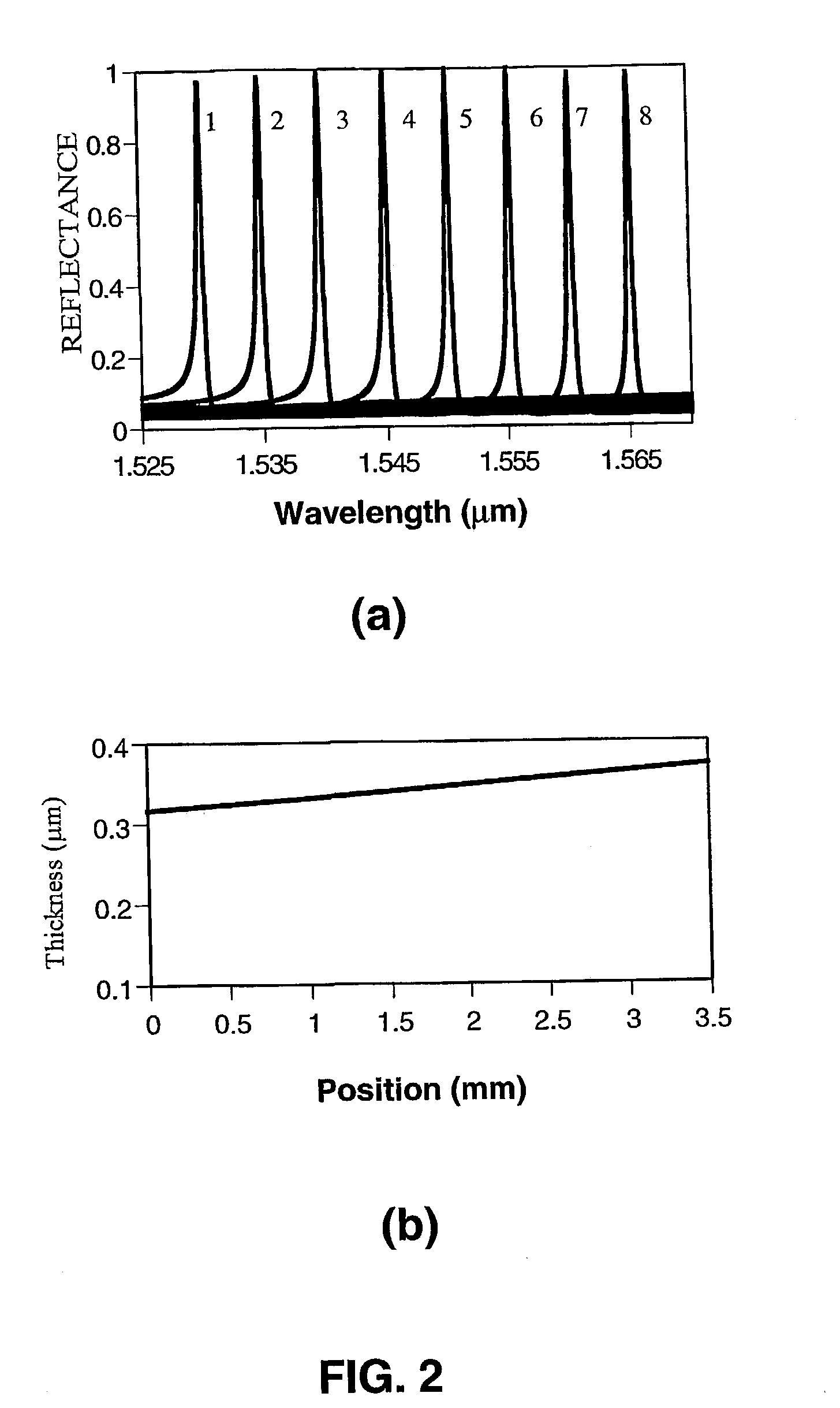
[0037]In the invention shown in FIG. 5, a wavelength selectable optical device is externally aligned to a laser array to achieve multi-wavelength outputs. The MWL array in this embodiment is formed by a body 15, a plurality of identical active elements 16, a high-reflection coating 31 on one of the common facets of the body, a micro-lens array 30 on the other side of the body, and a wavelength selectable optical device 10. Similarly, the optical device 10 contains a substrate 11, a non-uniform waveguide layer (thickness varied or refractive index varied) 13, and a grating layer 14. The number of the micro-lenses in the lens array 30 is equal to the number of the active elements 16, and the distance between two adjacent lenses is the same as that of two adjacent active elements 16. The micro-lens array 30 is aligned with one of the common emitting facets of the active elements 16 so that the light emitted from each of the active elements 16 is collimated by a corresponding micro-lens...

first embodiment

[0040]Laser resonant cavities in this embodiment are formed by the high-reflection facet 41, the active elements 16, the polished facet 42, and the optical device 10. The polished facet 42 is able to bend the light from each of the active elements 16 by 90 degrees. The bent light then strikes the optical device 10 in a corresponding position, which feeds the light back at a selected wavelength. When the light reaches the facet 42 again, it is bent again, traveling back into the active element 16. Since the reflectivity of the coated facet 41 is close to 100%, the light emitted from this facet is negligible. The optical device 10 located on the wafer surface can be designed with reflectivity less than 100% so that it also functions as laser output couplers. Thus, emission of laser lights from the surface of the wafer is achieved. For the same reasons discussed for the first embodiment, the outputs contain MWL beams. This structure is suitable for mass production. The 45-degree polish...


PUM


Abstract

A multi-wavelength laser array is achieved by using a wavelength selectable optical device as a feedback mirror for a plurality of lasers. The wavelength of reflected light from the optical device depends upon the parameters in the local reflection positions of the optical device along the direction as determined by guided-mode resonance. Thus, the multi-wavelength laser array is able to emit a plurality of laser beams with desired wavelengths, each within the gain curve of its active element.

Description

FIELD OF INVENTION[0001]The present invention relates generally to optical networks, and more particularly to multi-wavelength laser technology.BACKGROUND OF THE INVENTION[0002]Multi-wavelength lasers (MWLs) are useful in providing multiple-channel light sources for optical networks, especially for dense wavelength division multiplexing (DWDM) systems. The desirable features of MWLs used for DWDM systems include compact design, high stability in the output wavelengths and wavelength spacing, reasonable output power, wide wavelength range and narrow linewidth for a large channel capacity, convenience of modulating individual wavelength at a high rate, and easiness of manufacture. In addition, the wavelength locking mechanisms of laser sources should be as simple as possible. No existing MWL provides all those features largely because of the limitations in current laser technologies.[0003]A number of MWL technologies have been investigated, and they can be generally classified into tw...

Claims


Application Information

Patent Timeline
IPC IPC(8): G02B6/12H01S3/04H01S3/06H01S3/08H01S3/23H01S5/026H01S5/40
CPCH01S5/026H01S5/4087H01S5/4062H01S5/146
Inventor LIU, ZHONGSHAN
Owner LIU ZHONGSHAN
Why Eureka
Try Eureka