Infrared radiation emitter

a radiation emitter and infrared technology, applied in the field of infrared radiation sources, can solve the problems of fragile and easily broken indium seals, limited power of sources, and extremely short life span of nicrs, so as to improve the appreciation of present contributions to the ar

Active Publication Date: 2006-10-17
WOOD DONALD S
View PDF13 Cites 10 Cited by
  • Summary
  • Abstract
  • Description
  • Claims
  • Application Information

AI Technical Summary

Benefits of technology

[0028]It is therefore an object and advantage of the present invention to provide an IR source having higher power with greater modulation depth than presently available. Applications include medical and industrial gas detection and analysis and many other miscellaneous applications such as identification of plastics and trace contaminants in fluids, etc. Having a higher power source with the same detector will increase the overall signal-to-noise ratio and therefore the sensitivity of the measurement instrument. Alternatively, a higher power source will allow the device manufacturer to use a less expensive detector to achieve the same signal-to-noise ratio in the system. This is advantageous because detectors are relatively more expensive than sources, while low sensitivity detectors are relatively less expensive than high sensitivity detectors.
[0029]Other novel features which are characteristic of the invention, as to organization and method of operation, together with further objects and advantages thereof will be better understood from the following description considered in connection with the accompanying drawings, in which preferred embodiments of the invention are illustrated by way of example. It is to be expressly understood, however, that the drawings are for illustration and description only and are not intended as a definition of the limits of the invention. The various features of novelty that characterize the invention are pointed out with particularity in the claims annexed to and forming part of this disclosure. The invention does not reside in any one of these features taken alone, but rather in the particular combination of all of its structures for the functions specified.
[0030]There has thus been broadly outlined the more important features of the invention in order that the detailed description thereof that follows may be better understood, and in order that the present contribution to the art may be better appreciated. There are, of course, additional features of the invention that will be described hereinafter and which will form additional subject matter of the claims appended hereto. Those skilled in the art will appreciate that the conception upon which this disclosure is based readily may be utilized as a basis for the designing of other structures, methods and systems for carrying out the several purposes of the present invention. It is important, therefore, that the claims be regarded as including such equivalent constructions insofar as they do not depart from the spirit and scope of the present invention.
[0031]Further, the purpose of the Abstract is to enable the U.S. Patent and Trademark Office and the public generally, and especially the scientists, engineers and practitioners in the art who are not familiar with patent or legal terms or phraseology, to determine quickly from a cursory inspection the nature and essence of the technical disclosure of the application. The Abstract is neither intended to define the invention of this application, which is measured by the claims, nor is it intended to be limiting as to the scope of the invention in any way.
[0032]Certain terminology and derivations thereof may be used in the following description for convenience in reference only, and will not be limiting. For example, words such as “upward,”“downward,”“left,” and “right” would refer to directions in the drawings to which reference is made unless otherwise stated. Similarly, words such as “inward” and “outward” would refer to directions toward and away from, respectively, the geometric center of a device or area and designated parts thereof. References in the singular tense include the plural, and vice versa, unless otherwise noted.

Problems solved by technology

The source has good modulation but is limited to very low power.
While this device advances significantly over the prior art, an indium seal is fragile and easily broken, and any elastomer (i.e., pliable) coating employed to reduce the fragility will interfere with the use of a heat sink to control the temperature of the lamp.
However, NiCr has an extremely short life span when operated above 800 degrees C. Thus the need for a durable and long lasting IR emitter having higher power and greater modulation depth has not been adequately addressed.

Method used


Image

  • Infrared radiation emitter
  • Infrared radiation emitter
  • Infrared radiation emitter

Examples


embodiment 100

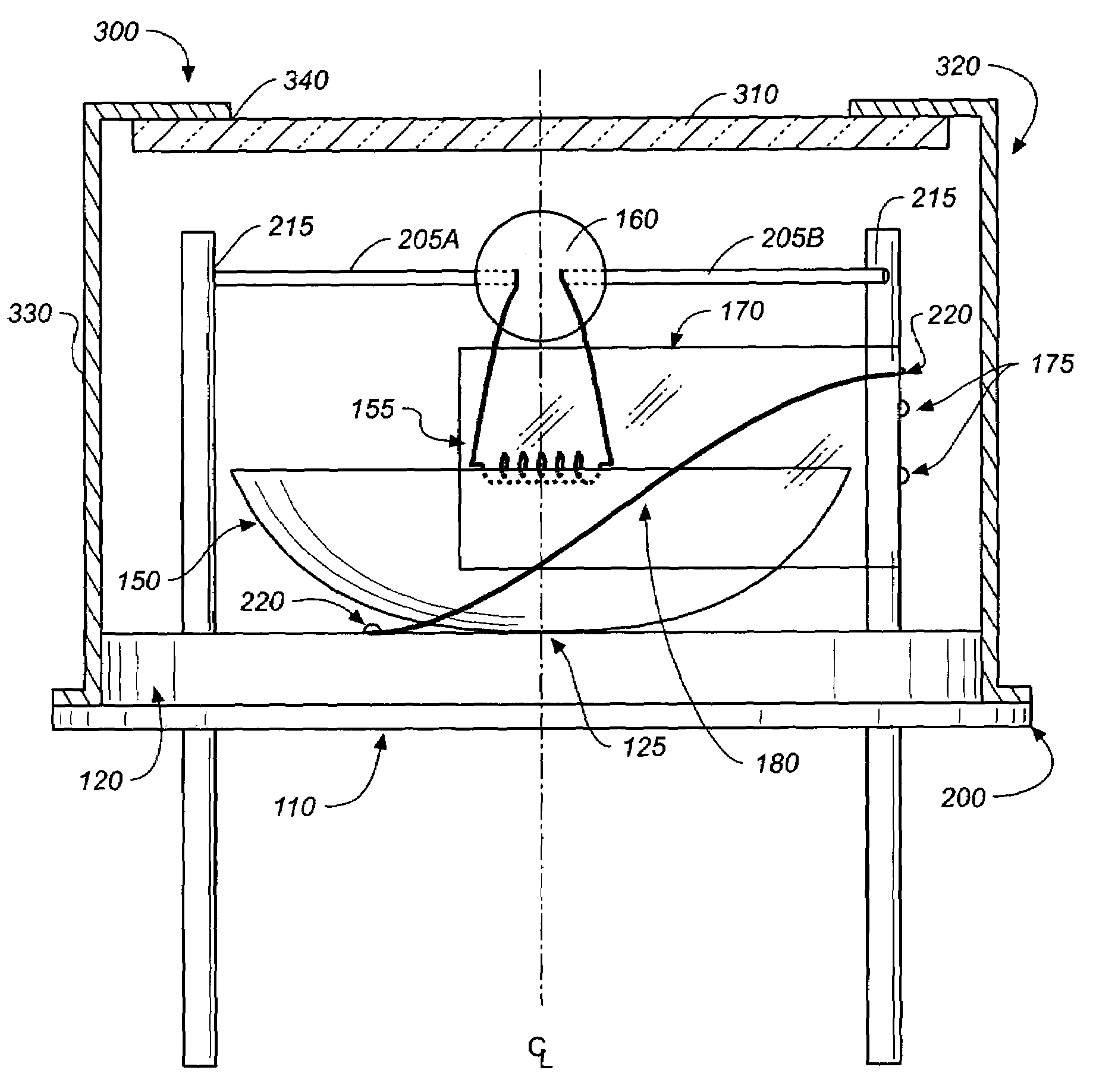
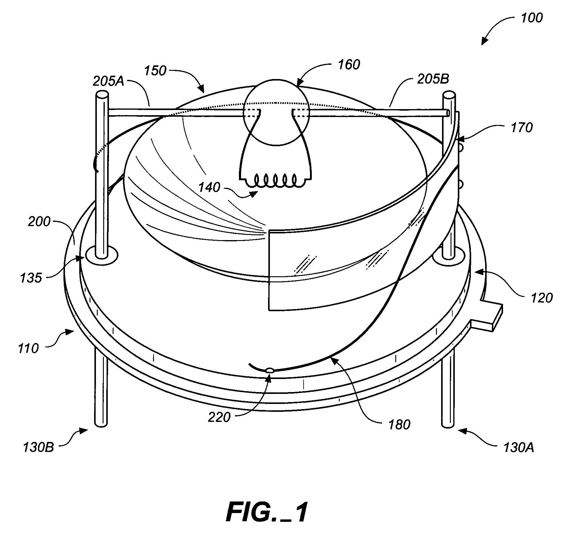
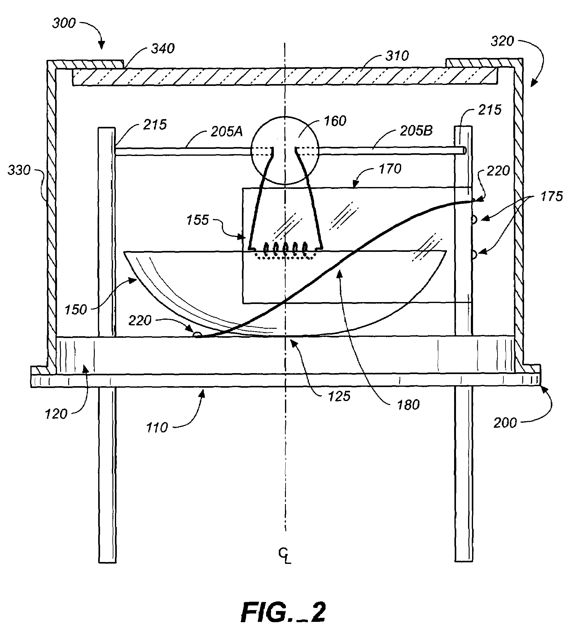
[0081]FIGS. 1–3 illustrate a first preferred embodiment 100 of the infrared radiation emitter. This embodiment is primarily for use with a pulsable source as it includes delicate tungsten filaments with leads stabilized in a glass bead. These views show that the inventive apparatus includes an industrial standard TO-8 or similar header 110 having a base 120 with first and second electrical input (feed-through) pins 130A, 130B, or simply input pins. The input pins pass through glass seals 135 in the base. The input pins supply electrical current through leads and to a fine looped or coiled tungsten filament 140 suspended above a gold-plated reflecter150 at the reflector's focal point 155 by a glass bead filament support 160. An oxygen getter strip170 and a fine NiCr wire 180 are also disposed on the base, and these elements, along with the tungsten wire, are all covered with a sapphire, calcium fluoride, or zinc selenide (ZnSe) cap and window assembly 300, resistance welded to the ba...

embodiment 700

[0097]FIG. 6 shows a third preferred embodiment 700 of the improved infrared radiation emission source of the present invention. This embodiment is primarily for higher power steady state sources containing larger tungsten filaments and employs a different configuration for mounting the tungsten filament coil 710 to the electrical input (feed-through) pins 720, 730, on the header 740. Again, cross bars 750, 760, preferably fabricated from molybdenum, are welded to the input pins on the header in the manner described above. The tungsten filament is attached to the cross bars by compressing small molybdenum sleeves 770 around the ends of the tungsten lead wires so that it makes a tight mechanical connection; then the compressed sleeves are welded to the cross bars. The filament coil 710 is positioned directly below the cross bars at the focal point 780 of the reflector 790. Again, the getter 800 is welded to one of the input pins. Other orientations of the coil and cross bars are poss...


PUM

PropertyMeasurementUnit
wavelengthaaaaaaaaaa

Abstract

An emitting source capable of radiating substantial energy in the near infrared spectrum and suitable for use in non-dispersive infrared gas analyzers or other devices is described. Operation can be steady state (DC) or pulsed at high frequency with excellent modulation characteristics. The device consists of a tungsten filament mounted across the pins of a small transistor outline header and centered at the focal point of a parabolic or other shaped reflector. The header assembly is enclosed by a resistance-welded cap and window assembly having a specially sealed sapphire or other suitable IR transmissive window. Fundamental to the operation of the inventive IR emitter is the incorporation of a getter within the header package configured to prevent oxidation degradation of the tungsten filament. An inert gas backfill limits filament evaporation and further extends apparatus lifetime.

Description

CROSS REFERENCE TO RELATED APPLICATIONS[0001]The present application claims the benefit of the filing dates of U.S. Provisional Patent Application Ser. No. 60 / 537,826, filed Jan. 20, 2004, and U.S. Provisional Patent Application Ser. No. 60 / 473,498, filed May 27, 2003.STATEMENT REGARDING FEDERALLY SPONSORED RESEARCH OR DEVELOPMENT[0002]Not applicable.REFERENCE TO A MICROFICHE APPENDIX[0003]Not applicable.TECHNICAL FIELD[0004]The present invention relates generally to infrared radiation sources, and particularly to an emitter which radiates in the near infrared spectrum for use in non-dispersive infrared (NDIR) gas analyzers and other devices requiring an infrared source.BACKGROUND INFORMATION AND DISCUSSION OF RELATED ART[0005]It is known to employ infrared (IR) emitters in connection with dispersive and non-dispersive-type infrared spectrometers and gas analyzers. Applications are manifold, including medical and industrial gas detection and analysis. IR sources are employed in the ...

Claims


Application Information

Patent Timeline
Patent Type & Authority Patents(United States)
IPC IPC(8): A61N5/06G01J1/08G01N21/35H01K1/18H01K1/26H01K1/28H01K1/50H01K1/54H01K7/00
CPCG01J1/08H01K1/18H01K1/26H01K1/28H01K1/50H01K1/54H01K7/00G01N21/35G01N2201/06186G01N21/359
Inventor WOOD, DONALD S.
Owner WOOD DONALD S
Why Eureka
Try Eureka