
Solid electrolytic capacitor and method of manufacturing the same

a technology of electrolytic capacitors and solid electrolytic capacitors, which is applied in the direction of fixed capacitor details, variable capacitors, fixed capacitors, etc., can solve the problems of increased lc (leakage current), decreased reliability, and increased esr (equivalent series resistance), and achieves low esr, high reliability, and high capacitance.

Active Publication Date: 2007-02-20
SANYO ELECTRIC CO LTD
View PDF7 Cites 29 Cited by
  • Summary
  • Abstract
  • Description
  • Claims
  • Application Information

AI Technical Summary

Benefits of technology

The present invention provides a solid electrolytic capacitor with high capacitance, low ESR, and high reliability. The capacitor has a conductive polymer compound as a solid electrolyte and includes an anode body, a dielectric oxide coating, a first conductive polymer compound layer, a silane coupling agent treatment layer, and a second conductive polymer compound layer. The spacing between the layers can be at least 10 nm and smaller than 100 μm, and the first and second conductive polymer compound layers can be formed using chemical oxidative polymerization or electrolytic oxidative polymerization. The method of manufacturing the capacitor includes the steps of forming a dielectric oxide coating, forming a first conductive polymer compound layer, forming a silane coupling agent treatment layer, and forming a second conductive polymer compound layer. The technical effects of the invention include high capacitance, low ESR, and high reliability.

Problems solved by technology

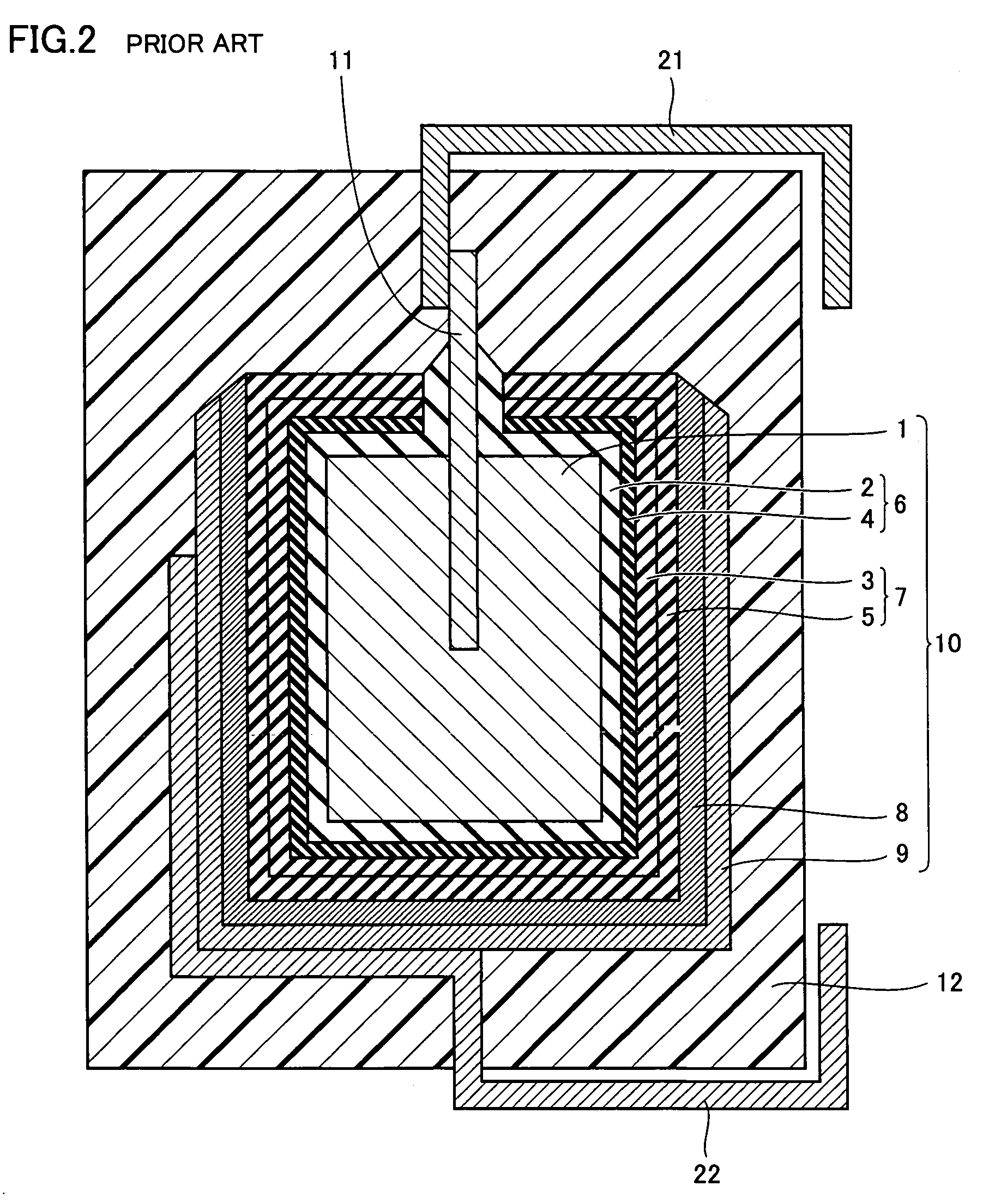
The solid electrolytic capacitor has a problem of a decrease in adhesion between a dielectric oxide coating, which is formed by oxidation of a surface of an anode body formed with a sintered body of a valve metal such as tantalum, niobium, titanium, or aluminum, and a solid electrolyte layer formed on the dielectric oxide coating, which results in an increased LC (Leaked Current), an increased ESR (Equivalent Series Resistance) and decreased reliability.

Method used


Image

  • Solid electrolytic capacitor and method of manufacturing the same
  • Solid electrolytic capacitor and method of manufacturing the same
  • Solid electrolytic capacitor and method of manufacturing the same

Examples


example 1

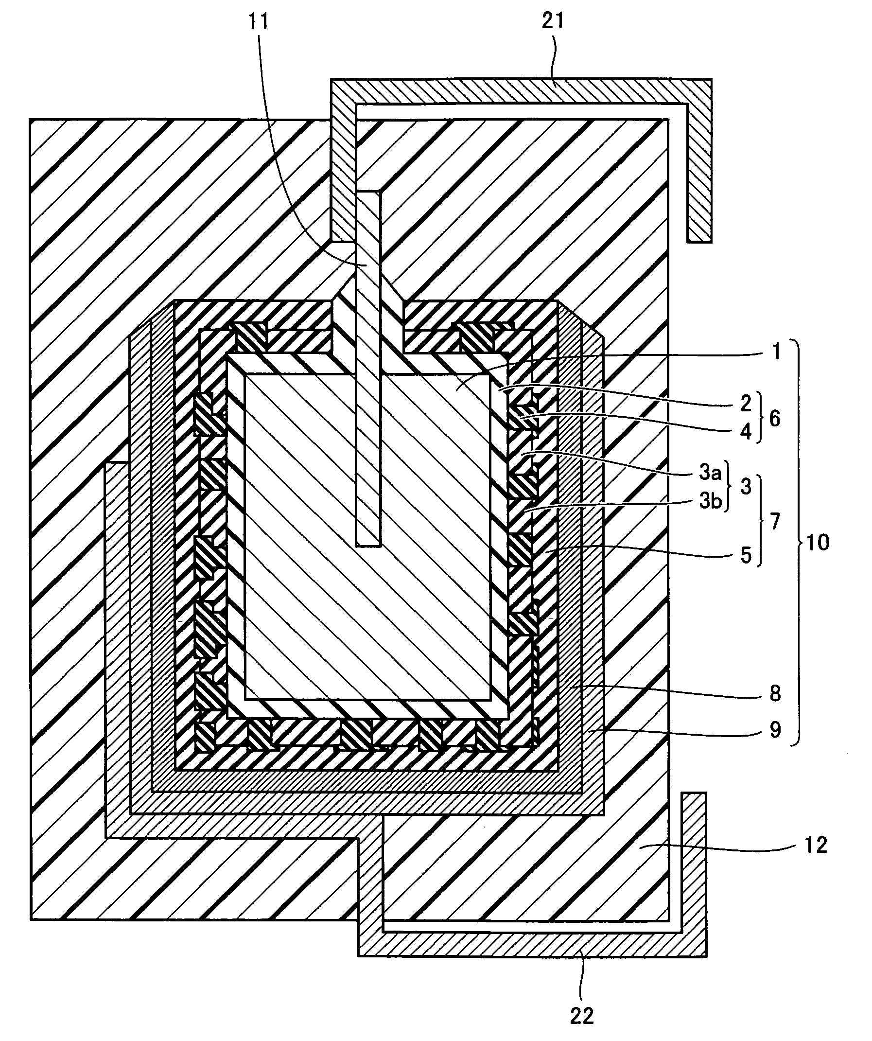
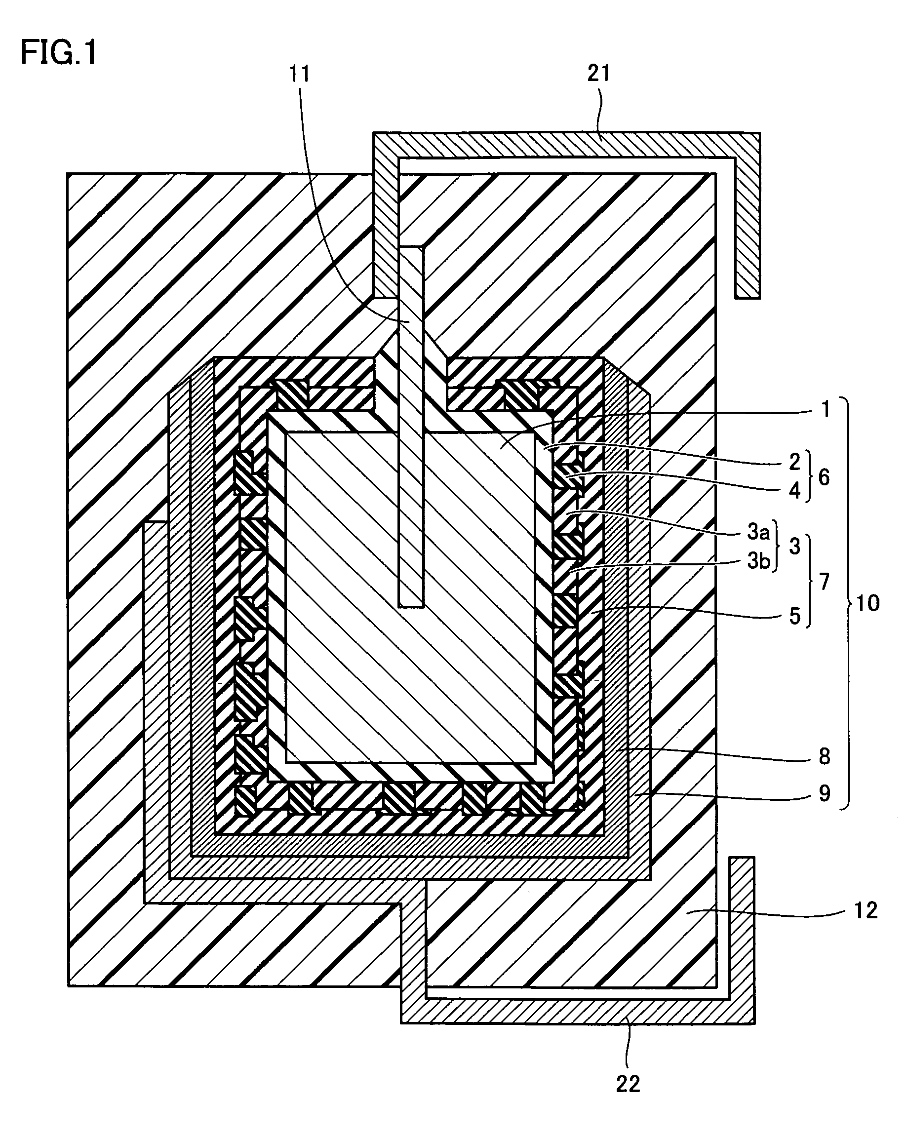
[0033]Referring to FIG. 1, for anode body 1 of a rectangular parallelepiped of 2.3 mm×1.8 mm×1.0 mm formed with sintered tantalum (Ta), which had anode lead member 11 inserted thereto from one end surface thereof (2.3 mm×1.0 mm), electrolytic oxidation was performed in a phosphoric acid solution of 65° C. by applying a constant voltage of 10 V for 10 hours to form dielectric oxide coating 2.

[0034]Then, an element formed as such was successively immersed at 25° C. in an ethanol solution including 3.0 M (a concentration in mol / liter, which is the same in the following) of pyrrole for 5 minutes and in a solution including 0.1 M of ammonium persulfate and 0.1 M of alkyl naphthalenesulfonic acid for 5 minutes to form first conductive polymer compound layer 3 on a portion of dielectric oxide coating 2. A spacing between portion layers 3a, 3b of first conductive polymer compound layer 3 measured with the SEM was at least 10 nm and smaller than 100 μm.

[0035]Then, the element was immersed in...


PUM

PropertyMeasurementUnit
constant voltageaaaaaaaaaa
currentaaaaaaaaaa
resistanceaaaaaaaaaa

Abstract

A solid electrolytic capacitor using a conductive polymer compound as a solid electrolyte includes an anode body, a dielectric oxide coating formed on a surface of the anode body, a first conductive polymer compound layer formed on a portion of the dielectric oxide coating, a silane coupling agent treatment layer formed at least on a portion of the dielectric oxide coating on which the first conductive polymer compound layer is not formed, and a second conductive polymer compound layer formed on the first conductive polymer compound layer and the silane coupling agent treatment layer. With this, a solid electrolytic capacitor having a high capacitance, a low ESR and high reliability and a method of manufacturing the solid electrolytic capacitor can be provided.

Description

BACKGROUND OF THE INVENTION[0001]1. Field of the Invention[0002]The present invention relates to a solid electrolytic capacitor using a conductive polymer compound as a solid electrolyte and a method of manufacturing the solid electrolytic capacitor.[0003]2. Description of the Background Art[0004]In connection with size and weight reductions of electric equipment in recent years, a small capacitor of a large capacity for high frequencies has come to be required. As such a capacitor, a solid electrolytic capacitor using a conductive polymer compound to form a solid electrolyte layer has been proposed.[0005]The solid electrolytic capacitor has a problem of a decrease in adhesion between a dielectric oxide coating, which is formed by oxidation of a surface of an anode body formed with a sintered body of a valve metal such as tantalum, niobium, titanium, or aluminum, and a solid electrolyte layer formed on the dielectric oxide coating, which results in an increased LC (Leaked Current), ...

Claims


Application Information

Patent Timeline
Patent Type & Authority Patents(United States)
IPC IPC(8): H01G5/013H01G4/06H01G9/02
CPCH01G9/028H01G11/56H01G9/15Y02E60/13
Inventor KOBAYASHI, NOBUYUKI
Owner SANYO ELECTRIC CO LTD
Learn More