
Formed substrate used for solid electrolytic capacitor, production method thereof and solid electrolytic capacitor using the substrate

a solid electrolytic capacitor and substrate technology, applied in the direction of oxide conductors, conductors, non-metal conductors, etc., can solve the problems of not meeting the theoretical electrostatic capacitance, the electrostatic capacitance of conventional aluminum solid electrolytic capacitors at a forming voltage less than 20 v, etc., to improve the electrostatic capacitance, reduce the dispersion of capacitor performance, and improve the effect of electrostatic capacitan

Inactive Publication Date: 2007-04-03
MURATA MFG CO LTD
View PDF16 Cites 6 Cited by
  • Summary
  • Abstract
  • Description
  • Claims
  • Application Information

AI Technical Summary

Benefits of technology

[0012]Accordingly, the object of the present invention is to provide an electrolytic capacitor improved in the electrostatic capacitance and reduced in the dispersion of the capacitor performance, where the oxide dielectric film on a formed substrate is surface-treated to yield a dielectric film such that an electrically conducting substance provided on the film can contact with the film over a sufficiently large contact area with good adhesion.
[0013]As a result of extensive investigations to solve the above-described problems, the present inventors have found that when a formed foil having thereon an aluminum oxide dielectric film covered by an oxide comprising Si (silicon), a valve-acting metal and O (oxygen), for example, Si, Al and O, the area coverage of a solid electrolyte (electrically conducting polymer) on the dielectric film is increased, the adhesive property therebetween and the like are improved, the electrostatic capacitance of the capacitor is in turn increased, and the dispersion of electrostatic capacitance among individual capacitors and the leakage current are reduced.
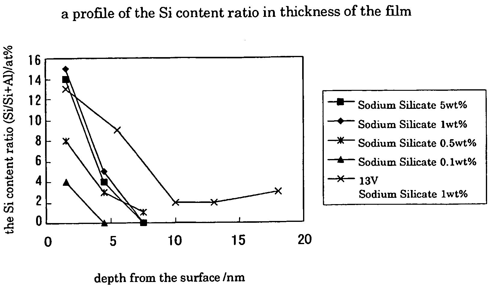
[0014]Moreover, the present inventors have found that by using a formed foil having a dielectric film of aluminum oxide whose surface is modified with Si and containing Si inside wherein the amount of Si decreases continuously toward the inner part in some regions, the area coverage of a solid electrolyte (electrically conducting polymer) on the dielectric film is increased and the adhesive property between the solid electrolyte and the dielectric film is improved to increase the electrostatic capacitance while the dispersion of electrostatic capacitance among individual capacitors and the leakage current are reduced. Still further, the present inventors have found that it is more preferable to use a formed foil having regions where the continuous decrease of Si content ratio from the surface toward the inner part, which is measured by TEM-EDX(TEM: transmission electron microscope, EDX: energy dispersive X-ray spectroscopy), occurs at a specific rate.

Problems solved by technology

This method is effective for a formed foil obtained by the electrochemical forming at a forming voltage of 20 to 300 V but fails in increasing the electrostatic capacitance of a low-voltage foil obtained at a forming voltage of less than 20 V.
However, the electrostatic capacitance of conventional aluminum solid electrolytic capacitors does not agree with the theoretical electrostatic capacitance (C) of a formed aluminum foil (C=εA / t, wherein ε is a dielectric constant of an aluminum oxide dielectric material, A is a surface area of a dielectric layer and t is a thickness of a dielectric material).
This phenomenon is considered to occur because the thickness and dielectric constant of the dielectric film, the area coverage and adhesion of the solid electrolyte (electrically conducting substance) on or to the dielectric film, and the like are insufficient in conventional electrochemical forming techniques.

Method used


Image

  • Formed substrate used for solid electrolytic capacitor, production method thereof and solid electrolytic capacitor using the substrate
  • Formed substrate used for solid electrolytic capacitor, production method thereof and solid electrolytic capacitor using the substrate
  • Formed substrate used for solid electrolytic capacitor, production method thereof and solid electrolytic capacitor using the substrate

Examples


example 1

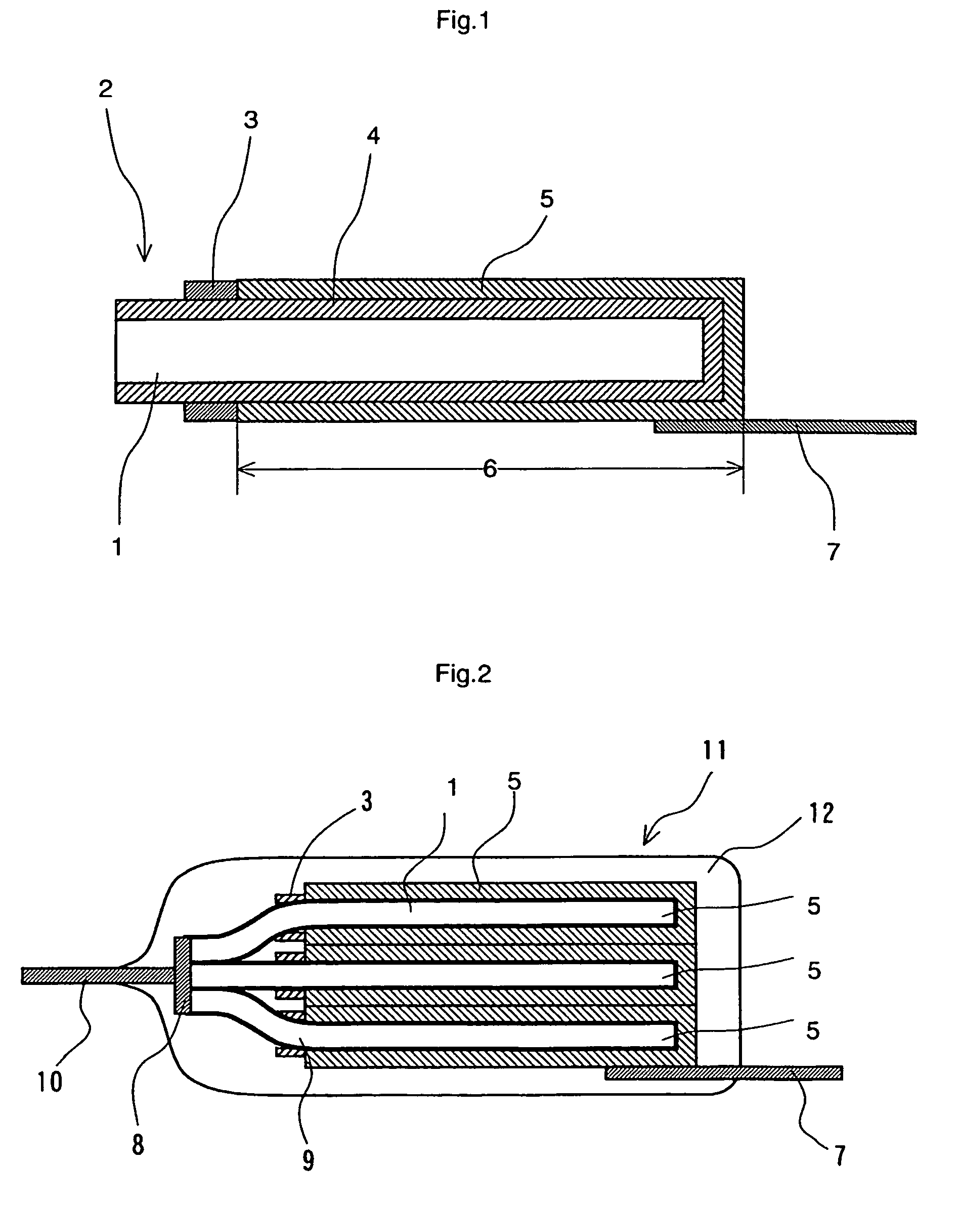
[0095]A formed aluminum foil (110LJ22B4Vf, trade name, produced by Japan Capacitor Industrial Co., Ltd. (JCC)) (rated film withstand voltage: 4 Vf) was cut and divided into the cathode part and the anode part by a masking material (3). The side working out to a cathode part was electrochemically formed with an aqueous 5 mass % oxalic acid solution at 25° C. for 120 seconds and then washed with water.

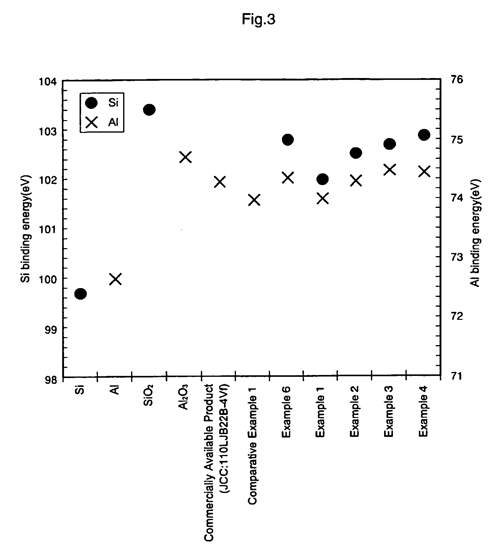
[0096]Thereafter, the foil was electrochemically formed using an aqueous 0.1 mass % sodium silicate solution under the conditions such that the temperature was 40° C., the voltage was 4 V, the current density was 5 mA / cm2 and the current passing time was 10 minutes. FIGS. 3 and 4 show the relationship of Si (101.97 eV), O (530.94 eV) and Al (73.98 eV) binding energy values when the foil at this stage was analyzed by XPS.

[0097]Subsequently, the resulting formed foil was heat-treated at 350° C. for 3 minutes and then electrochemically formed using an aqueous 10 mass % ammonium adipate solu...

example 2

[0099]A formed aluminum foil (110LJ22B4Vf, trade name, produced by Japan Capacitor Industrial Co., Ltd. (JCC)) (rated film withstand voltage: 4 Vf) was cut and divided into the cathode part and the anode part by a masking material (3). The side working out to a cathode part was electrochemically formed with an aqueous 5 mass % oxalic acid solution at 25° C. for 120 seconds and then washed with water.

[0100]Subsequently, a capacitor was manufactured by the same operation as in Example 1 except for using an aqueous 0.5 mass % sodium silicate solution in place of an aqueous 0.1 mass % sodium silicate solution. The obtained capacitor was measured on the electrostatic capacitance and the leakage current property. The results are shown in Table 1. FIGS. 3 and 4 show the relationship of Si (102.50 eV), O (531.26 eV) and Al (74.28 eV) binding energy values when the foil at this stage was analyzed by XPS.

example 3

[0101]A formed aluminum foil (110LJ22B4Vf, trade name, produced by Japan Capacitor Industrial Co., Ltd. (JCC)) (rated film withstand voltage: 4 Vf) was cut and divided into the cathode part and the anode part by a masking material (3). The side working out to a cathode part was electrochemically formed with an aqueous 5 mass % oxalic acid solution at 25° C. for 120 seconds and then washed with water.

[0102]Subsequently, a capacitor was manufactured by the same operation as in Example 1 except for using an aqueous 1.0 mass % sodium silicate solution in place of an aqueous 0.1 mass % sodium silicate solution. The obtained capacitor was measured on the electrostatic capacitance and the leakage current property. The results are shown in Table 1. FIGS. 3 and 4 show the relationship of Si (102.68 eV), O (531.39 eV) and Al (74.48 eV) binding energy values when the foil at this stage was analyzed by XPS.


PUM

PropertyMeasurementUnit
binding energyaaaaaaaaaa

Abstract

A formed substrate, wherein the surface of the valve-acting metal having a dielectric film is at least partially covered with an oxide comprising Si, valve-acting metal element and oxygen, preferably, wherein the content of Si in the formed foil having an aluminum oxide dielectric film decreases continuously from the surface of the dielectric film toward the inner part in some regions in the aluminum dielectric film thickness; a method for producing the formed substrate; and a solid electrolytic capacitor comprising a solid electrolyte on the formed substrate. A solid electrolytic capacitor manufactured by using a formed substrate according to the present invention, improved in adhesion to an electrically conducting polymer (solid electrolyte) with its area coverage contacting the polymer being sufficiently large, is increased in the electrostatic capacitance among individual capacitors and improved in the LC yield as compared with capacitors otherwise manufactured.

Description

CROSS-REFERENCE TO RELATED APPLICATIONS[0001]This application is based on the provisions of 35 U.S.C. Article 111(a) with claiming the benefit of filing dates of U.S. provisional application Ser. No. 60 / 299,769 filed on Jun. 22, 2001 and U.S. provisional application Ser. No. 60 / 322,426 filed on Sep. 17, 2001, under the provisions of 35 U.S.C. 111(b), pursuant to 35 U.S.C. Article 119(e)(1).TECHNICAL FIELD[0002]The present invention relates to a valve-acting metal having a dielectric film, particularly a formed foil having an aluminum oxide dielectric film, which is at least partially covered with a specific oxide, production method thereof, and also relates to an electrolytic capacitor using the metal material. More specifically, the present invention relates to a valve-acting metal formed foil having a dielectric film covered with an oxide comprising Si, valve-acting metal and oxygen(O), for example, a formed aluminum foil having an aluminum oxide dielectric film at least partially...

Claims


Application Information

Patent Timeline
Patent Type & Authority Patents(United States)
IPC IPC(8): H01G9/00H01B1/08H01B1/12H01B1/00H01G9/04H01G9/15
CPCH01G9/04H01G9/15H01G9/26Y10T428/24926Y10T29/417H01G9/048
Inventor KONUMA, HIROSHIYAMAZAKI, KATSUHIKOUMIKAWA, TAKENORIYAGI, MASAKAZUYAMASHITA, TAMOTSU
Owner MURATA MFG CO LTD
Learn More