Reflective Ag alloy film for reflectors and reflector provided with the same
a technology of reflector and alloy film, which is applied in the direction of optical elements, instruments, transportation and packaging, etc., can solve the problems of ag film not having satisfactory ability to withstand environmental conditions, ag film has difficulty in maintaining its function for a long period of use, and ag film has poor weather resistance and heat resistance. excellent, high reflectivity
- Summary
- Abstract
- Description
- Claims
- Application Information
AI Technical Summary
Benefits of technology
Problems solved by technology
Method used
Image

Examples
example 1
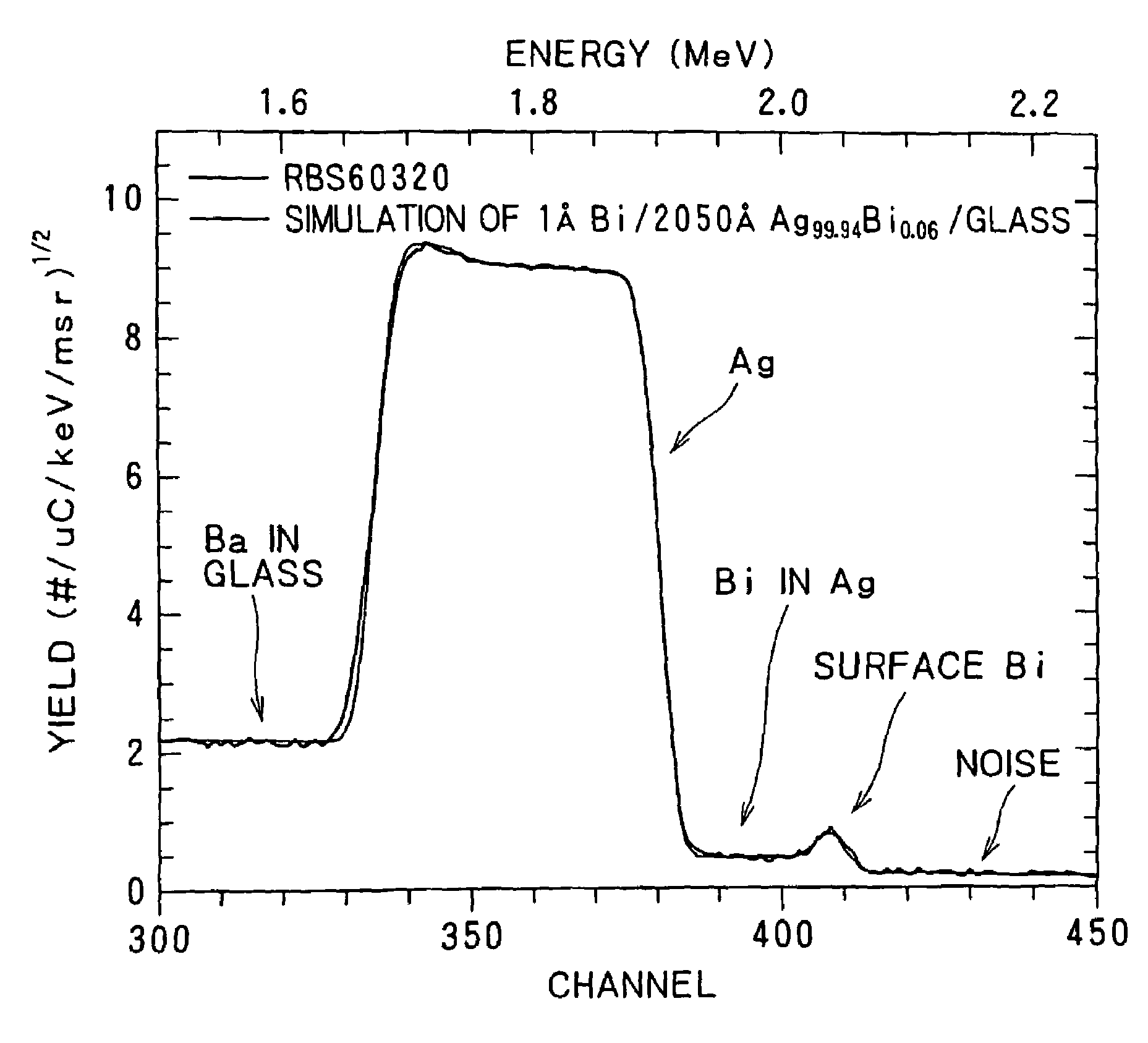
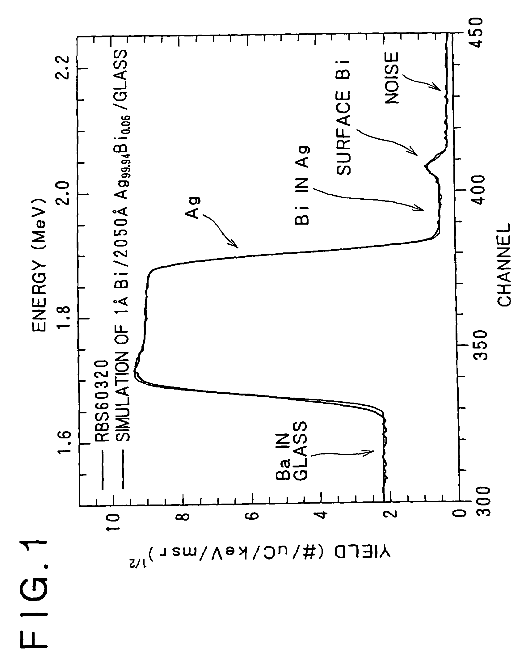
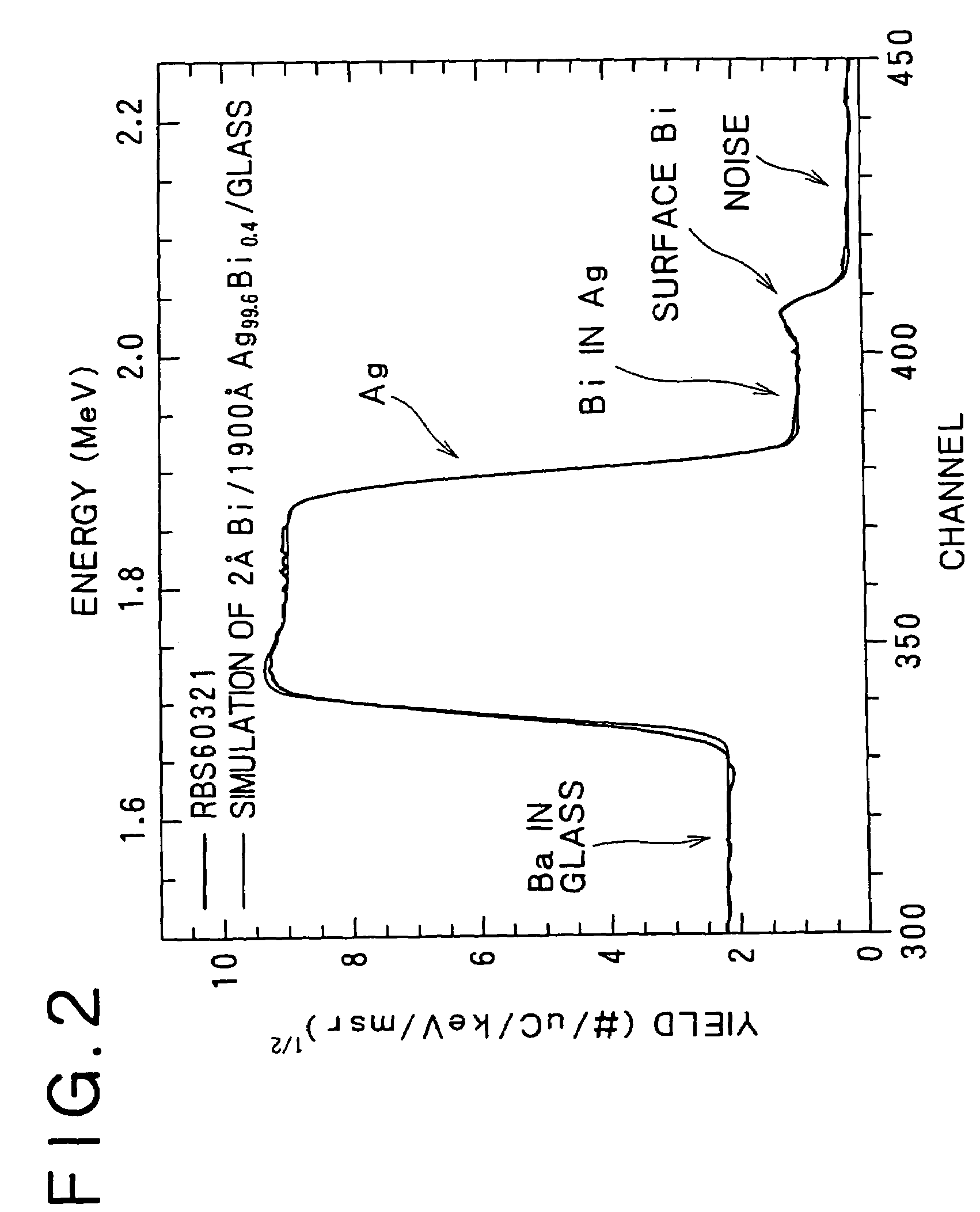
[0051]Ag—Bi alloy thin films of 2000 Å in thickness in Example 1, i.e., Ag alloy thin films containing Bi, were formed on glass substrates (#1737, Corning) of 50 mm in diameter and 0.7 mm in thickness, respectively, by a dc magnetron sputtering system. The Ag—Bi alloy thin films were deposited at a deposition rate in the range of 7.0 to 8.0 nm / s on the substrates kept at a room temperature in an Ar gas atmosphere of 1 to 3 mtorr. Anode-cathode distance was 55 m. A processing vessel was evacuated to a vacuum of 1.0×10⁻⁵ torr or below before starting the sputtering process. A Ag—Bi sputtering target of a Ag—Bi alloy having a Bi content of 0.1%, and a Ag—Bi sputtering target of a Ag—Bi alloy having a Bi content of 1.0% were used.
[0052]Ag—Bi alloy thin films thus formed were analyzed by Rutherford backscattering spectrometry (RBS) and x-ray photoelectron spectroscopy (XPS). Table 1 shows conditions for RBS.
[0053]Conditions for XPS
[0054]Apparatus: PHI5400MC, Palkin Elmer
[0055]X-ray sourc...
example 3
[0074]Ag—Bi—X alloy thin films of 2000 Å in thickness in Example 3, i.e., Ag alloy thin films respectively containing Bi and X (X=Au, Pd, Cu, Nd or Y), and Ag—Bi alloy film were formed on glass substrate (#1737, Corning) of 50 mm in diameter and 0.7 mm in thickness, respectively, by a dc magnetron sputtering system. Conditions for forming the Ag—Bi—X alloy thin film were the same as those for forming the Ag—Bi alloy thin film in Example 1. A Bi2O3 layer was formed on the surfaces of the Ag—Bi alloy thin film and the Ag—Bi—X alloy thin films.
[0075]The initial reflectivities of those Ag alloy thin films to light of 405 nm in wavelength were measured. The post-Ag-cohesion reflectivities of those Ag alloy thin films, i.e., reflectivities of the Ag alloy thin films after Ag cohesion, to light of 405 nm in wavelength were measured after keeping the Ag alloy thin films in a constant-temperature constant-humidity atmosphere of 90° C. and 80% RH for 48 hr. The surfaces of the Ag alloy thin f...
example 4
[0079]Laminated films were fabricated by depositing Bi oxide films of different thicknesses by a RF magnetron sputtering system on pure-Ag films formed by a dc magnetron sputtering system under the same process conditions as those for forming the Ag—Bi thin films in Example 1. A sputtering target of Bi oxide was used for depositing the Bi oxide films. Substrates were kept at a room temperature and the sputtering process was carried out in an Ar gas atmosphere of 3 mtorr. The thicknesses of the Bi oxide films were determined on the basis of film forming times required to form Bi oxide films respectively having different thicknesses in the range of 50 to 200 nm, and a thickness calibration curve.
[0080]Table 4 shows measured data. Since the reflectivity of the laminated film decreases with the increase of the thickness of the Bi oxide film, a desirable thickness of the Bi oxide film is 2.0 nm or below.
[0081]
TABLE 1ItemParametersBeam energy2300 keVIonsHe+Scattering angle170°Current30 nA...
PUM
| Property | Measurement | Unit |
|---|---|---|
| thickness | aaaaa | aaaaa |
| temperatures | aaaaa | aaaaa |
| RH | aaaaa | aaaaa |
Abstract
Description
Claims
Application Information
 - R&D
- Intellectual Property
- Life Sciences
- Materials
- Tech Scout
- Unparalleled Data Quality
- Higher Quality Content
- 60% Fewer Hallucinations
Browse by: Latest US Patents, China's latest patents, Technical Efficacy Thesaurus, Application Domain, Technology Topic, Popular Technical Reports.
© 2025 PatSnap. All rights reserved.Legal|Privacy policy|Modern Slavery Act Transparency Statement|Sitemap|About US| Contact US: help@patsnap.com