System and method for fiber optics based direct view giant screen flat panel display

a fiber optics and giant screen technology, applied in the field of fiber optics based direct view giant screen flat panel display, can solve the problems of lcd displays falling short in several areas when compared with the older crt technology, lcd technology cannot match the color reproduction accuracy of the crt technology, and lcd technology tends to have much smaller viewing angles, so as to achieve convenient transportation and storage

Active Publication Date: 2007-06-19
GENERAL DISPLAY
View PDF6 Cites 3 Cited by
  • Summary
  • Abstract
  • Description
  • Claims
  • Application Information

AI Technical Summary

Benefits of technology

[0029]One embodiment also provides a method and apparatus for reducing ambient light reflection and inter-pixel crosstalk which have detrimental effects on display contrast ratio under ambient light conditions. To this end a black backing layer and a black matrix are used to absorb ambient light and prevent crosstalk, and multilayer dielectric narrowband optical filters is used to differentially absorb undesired stray lights and allow selected lights to pass through. The effectiveness of such measures is greatly enhanced by the very small fill factor of the display elements in the proposed giant screen display, and by the narrowband nature of the laser diode emission.
[0032]In an alternative embodiment, the coupling tubes are vertical and in optical and mechanical contact with the column fibers. A piezoelectric micro-pump similar to one used in the inkjet head is employed for each row to inject transparent liquid droplet down the coupling tubes. The speeds of the droplets are maintained by an air pump which keeps a constant pressure difference between the front and back of the individual droplet. A near perfect optical coupling occurs at the instantaneous location of the droplet, redirecting the laser light of the diffuser. To reduce manufacturing cost, the piezoelectric micro-pumps for a plurality of rows can be integrated together into a single unit. The transparent walls of the coupling tube should have index of refraction slightly smaller than that of the main column fibers. The inner wall surface should be non-wetting for the liquid, and the surface tension of the liquid should be sufficiently strong to ensure that the liquid droplet can maintain its shape even when it is subjected to a pressure difference which propels it at a constant velocity.
[0035]Another embodiment provides a method for enhancing the dynamic contrast ratio of the video displays. Laser diodes inherently have an exceedingly high static contrast ratio which is defined as the ratio of the highest rumination to the lowest lamination that a pixel can display. Dynamic contrast ratio is defined as the contrast ratio of a pixel in the presence of surrounding pixels of various gray scale values. Dynamic contrast ratio is most strongly affected by adjacent / neighboring pixel crosstalk. The absence of faceplate of the present inventive display technology inherently minimizes inter-pixel crosstalk. Crosstalk is further minimized by erecting a black matrix barrier to ensure that laser lights from proximal and distal pixels are blocked and / or absorbed before they reach the diffuser screen. The black matrix structure extends also to the diffuser screen itself in order to absorb ambient light. The effectiveness of the black matrix structure is enhanced by the very small filling factor of the laser diode display.

Problems solved by technology

However, LCD displays fall short in several areas when compared with the older CRT technology.
First of all, LCD technology cannot match the accuracy of color reproduction of the CRT technology, because of its smaller color gamut, defined as the area inside the triangle formed by connecting its three primary colors.
Second, the LCD tends to have much smaller viewing angles, and thirdly, the LCD's dynamic range falls far short of that of the CRT technology.
However, the LCD technology is still progressing at a rapid pace.
Hence if a pair of mutually orthogonal polarizing filters are added on each side of the liquid crystal sandwich, the light that passes through the first polarizer will passes through the second polarizer if no external electric field is applied across the sandwich, but it will not be able to pass through the second polarizer if a strong enough electric field is applied.
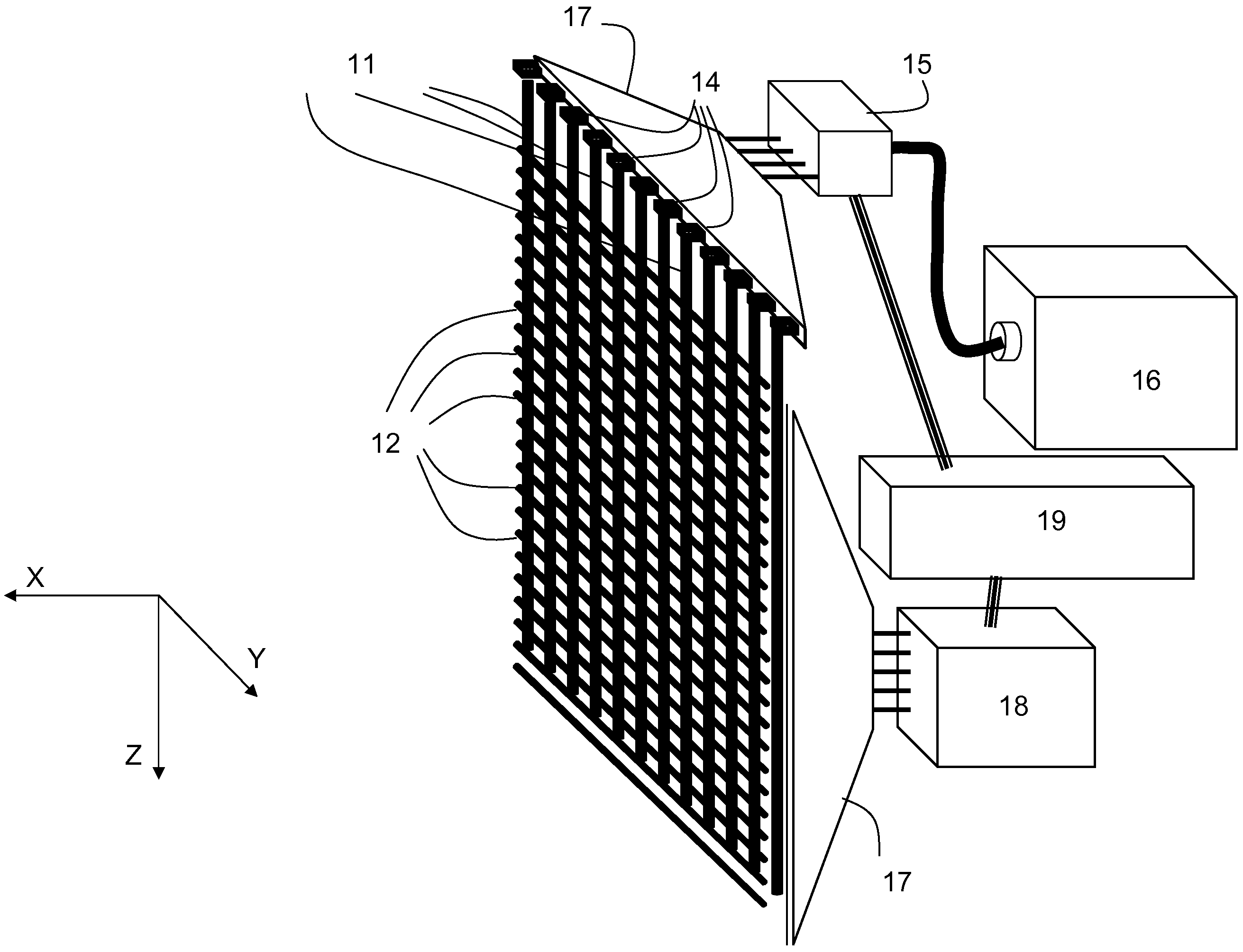
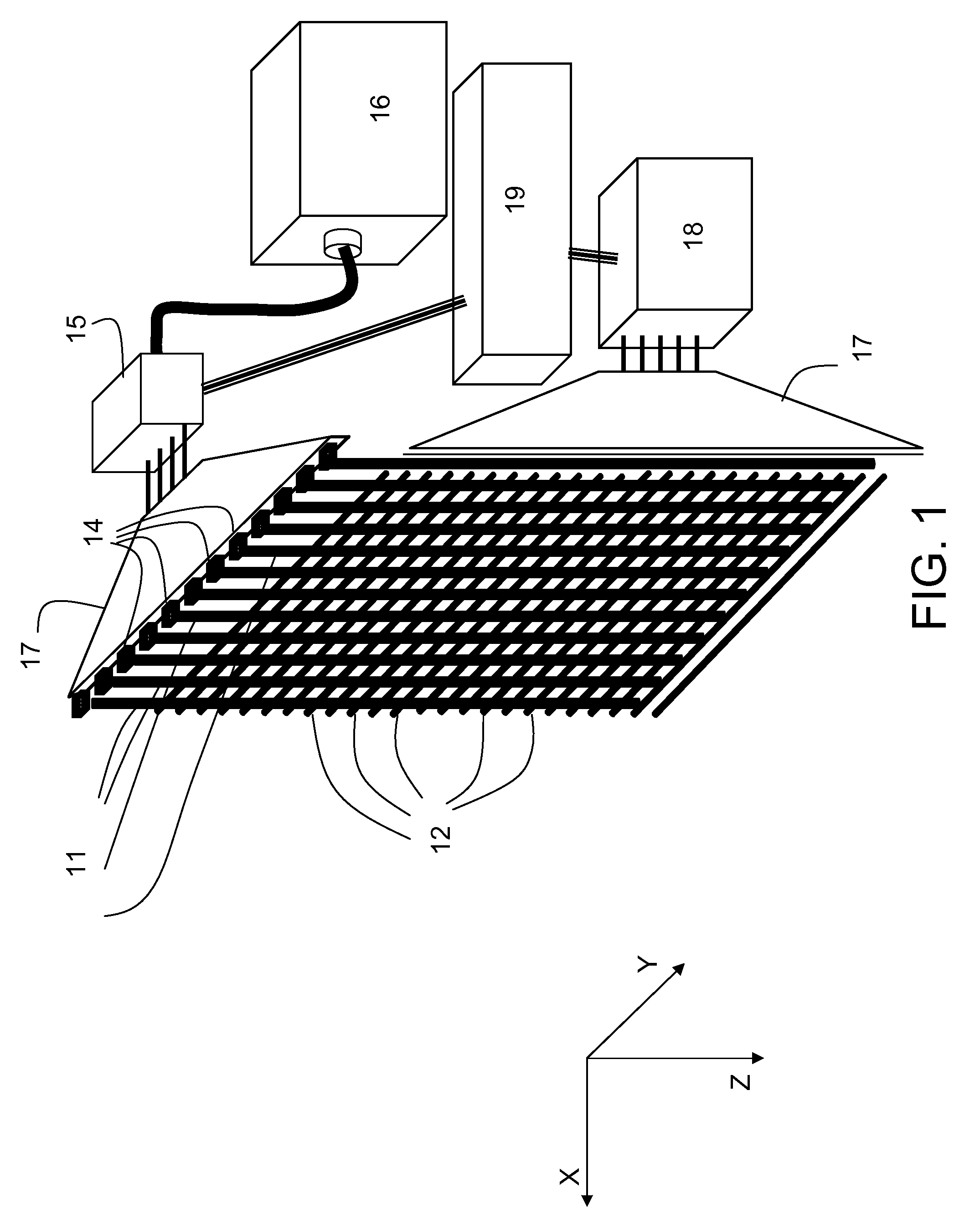
For a large display, it is clearly impractical to address the individual pixel separately because of the number of pixels involved.
They are relatively light weight and thin, and consume little power in comparison with CRT screens that they displaced.
However, LCD displays can't compete with CRTs when it comes to chromatic range, and response time.
It is inherently unstable since the ions and electrons have a tendency to recombine into neutrals.
However, since plasma displays require a large glass enclosure that can withstand atmospheric pressure, they tend to be a lot heavier and more costly to make, hence once the cost of the drive electronics gets lower as chip technology improves, the overall cost of plasma displays will eventually become higher than that of LCD displays.
However, since it would be difficult to manufacture tiny plasma pixels that are less than 0.5 mm in size, plasma display technology is only for big screens.
Also, since pulse coded modulation is used for brightness control, some image flickering is unavoidable.
Plasma displays also suffer from “burn-in”, a phenomenon shared by CRT technology.
Finally, compared to LCD screens, plasma displays consumes roughly twice the power of comparable sizes.
This can be attributed to the low emission efficiency of the plasma displays, despite having high optical efficiency.
Manufacturers prefer LCD because of the similarity to semiconductor fabrication techniques, whereas plasma screens require large vacuum glass enclosures which still have to be manufactured in the traditional way and does not benefit from Moorse' law.
The lack of backlighting device means that the display can be paper thin and can be bended.
However, currently OLED technology still surfers from long term stability and durability problems.
This is because OLED can not tolerate even the tiniest amount of moisture and / or oxygen and has to be perfectly sealed.
Also, the OLED compounds degrade over times, limiting the maximum life of a display.
OLED is also not an efficient light emitter.
Also, since the OLED needs not be turned on whenever a pixel is dark, the average power requirement is usually a lot less than that needed to light up all the OLED diodes on the screen, hence average power consumption of an OLED display is often lower than that of a comparable LCD screen.
The only major drawback is the longevity of the display materials.
Currently, because of the manufacturing difficulties, OLED displays are still confined mostly to screen sizes smaller than 10 inches, although larger displays have been demonstrated.
Both will increase the cost of the driver hardware dramatically.
Iridigm displays are light weight, low power consuming, and sharp.
Nevertheless, the usable viewing angles are still larger than those of the LCD technology.
The main drawbacks are the lack of backlighting, the durability (MEMS technology generally suffers from stiction problem, a problem associated with the tendency of the MEMS parts to stick together or slide poorly.
The problem gets worse with age), and the scalability to very large scale displays.
All the aforementioned display technologies suffer from the problems of high initial setup cost as well as high recurrent production costs.
Moreover, none of the technologies mentioned scale up very well to very large screen sizes.
In the case of plasma displays, such large glass panels also need to withstand the enormous atmospheric pressure, which escalates the cost of manufacturing such panels.
For LCD displays, the cost of active matrix addressing elements goes up dramatically with the screen size.
Although screen sizes of 102″ for PDP (plasma display panel) and 82″ for LCD have been demonstrated, their production costs will likely dissuade most people from buying them.
However, both still have to overcome their shortcomings in the area of durability and scalability.
However, the printing has to be done in the absence of moisture and oxygen, and the low conductivity of inkjet printed circuit board means that additional process is needed to enhance the conductivity when the display is scaled to such large sizes.
Even if all these can be overcome, the need to scale up the active matrix control electronics remains a problem which OLED shares with active matrix LCD displays.
Building a large Iridigm display would be extremely difficult since it would require a large scale MEMS manufacturing.
Current MEMS production technology can only produce small MEMS devices.
Even if such a display screen could be made, the pulse width modulation used in the passive matrix addressing is still a major problem since as the screen size increases; the MEMS light switches also become proportionally larger.
Since the response time of the MEMS switch is directly proportional to the size of the MEMS elements, for very large screen sizes the MEMS switches would fail to keep up with the fast pulse width modulation necessary to provide the gray scale resolution needed for high quality display images.
Such implementations are inherently costly and do not scale up well to large displays.
The cost of manufacturing and assembling such panels for large displays proves prohibitive.
None of the display technologies discussed above is particularly power efficient except the one by Iridigm, which currently can't be scaled up to large screen sizes.
As screen sizes increase, thermal management becomes a big issue which may necessitate the inclusion of active cooling at some stage.
Although Electroosmotic force is typically weaker than the electrostatic force of other embodiments, the fact that the fluid is overall neutral rather than being charged may be useful in environment where electrostatic discharge, or ESD, could be a problem.

Method used


Image

  • System and method for fiber optics based direct view giant screen flat panel display
  • System and method for fiber optics based direct view giant screen flat panel display
  • System and method for fiber optics based direct view giant screen flat panel display

Examples


Embodiment Construction

[0075]In the following detailed description of the present invention, numerous specific details are set forth in order to provide a thorough understanding of the present invention. However, it will become obvious to those skilled in the art that the present invention may be practiced without these specific details. In other instances, well-known methods, procedures, materials, components and circuitry have not been described in detail to avoid unnecessary obscuring aspects of the present invention. The detailed description is presented largely in terms of simplified two dimensional views. These descriptions and representations are the means used by those experienced or skilled in the art to concisely and most effectively convey the substance of their work to others skilled in the art.

[0076]Reference herein to “one embodiment” or an “embodiment” means that a particular feature, structure, or characteristics described in connection with the embodiment can be included in at least one e...


PUM


Abstract

An apparatus and method for displaying large format images, graphics, and videos. The apparatus comprise a layer of column oriented optical fibers, each fiber is illuminated at one end by at least one laser diode, and a second layer which sits in front of the first layer and is parallel to the first layer, whose projected area substantially overlap that of the first layer. The second layer comprises a plurality of optical fibers arranged in rows. In between the first and second layer sits a third layer of optical switching elements. Alternatively, the second layer can be a light diffusing layer. Laser lights emitted from the laser diodes travel in parallel along respective column fiber until they are redirected by optical switching elements which couple the laser lights within the column fibers to the row fibers or to the difflusing layer directly whereby they are scattered by the diffusing elements to reach the viewing audience. The small size of the fibers results in very small fill factor, allowing light absorbing matrix and backing layer to absorb ambient light effectively. The contrast ratio under ambient light condition is further enhanced by the use of multilayer dielectric optical filter to preferentially absorb ambient light.

Description

DESCRIPTION OF THE RELATED ART[0001]Displays are the pivotal components of modern information technology systems, ranging from large wall-mounted TVs and projection TV systems, through desktop flat-panel monitors and the ubiquitous notebook and laptop computers, to mobile phones, PDAs and wearable computing systems.[0002]The cathode ray tube (CRT) was the prevailing display technology roughly ten years ago; it was used in large and small screen TVs, projection TVs, desktop computer monitors, etc. Today the majority of the computer monitors, both for desktops or laptops, digital TVs, cell phones, PDAs, are dominated by technologies other than that of CRT. Only low end analogue TVs, and professional studio quality TV monitors, still employ CRT technology because of its low cost and superior picture quality for displaying images.[0003]Currently, LCD (liquid crystal display) is the predominant technology for displays. It is widely deployed in computer monitors, laptop computers, project...

Claims


Application Information

Patent Timeline
Patent Type & Authority Patents(United States)
IPC IPC(8): G02B6/26G02B6/36
CPCG09G3/001G02B6/3538G02B6/35G02B6/42G09F9/305G02B6/36
Inventor LEE, YEE CHUN
Owner GENERAL DISPLAY
Why Eureka
Try Eureka