
Parenteral products automation system (PPAS)

a technology of automation system and parenteral products, applied in the field of automatic systems, can solve the problems of harm to patients, slow and unreliable manual delivery, and exact but tedious responsibility of a highly skilled staff, and achieve the effect of enhancing the pressure barrier and simplifying the correction of problematic carriers

Inactive Publication Date: 2007-08-21
BAXTER ENGLEWOOD
View PDF10 Cites 67 Cited by
  • Summary
  • Abstract
  • Description
  • Claims
  • Application Information

AI Technical Summary

Benefits of technology

[0034]The drug specified is retrieved by a robotics arm from a gravity feed rack which was hand-fed prior to the initiation of the automated preparation. A sensor should be placed at the end of each column of drug storage to detect an empty rack and thus notify the operation system that the column needs to be replenished. As an alternative, inventory control software could manage the number of units present in the supply rack or column.
[0059]There are numerous criteria used in designing a carrier for pneumatic systems. It is preferable that the carrier be light, inexpensive and foolproof. Also, the carrier should be arranged so that it cannot be entered into a tube system when in an open position or open while in the tube. Such an arrangement ensures that the carrier is closed before it is entered into the system thereby limiting the possibilities that the carrier contents will be lost in the system and that the carrier will become lodged in the system. The carrier should preferably also be capable of carrying a maximum length of materials around given bends in the system and be capable of being locked in a closed position. A pair of ring seals (referred to also as accelerator, glide or travel rings, etc.) should be provided intermediate the ends of the carrier for guiding the carrier through a pneumatic tube system and for limiting air seepage past the carrier. End portions of the carrier should be tapered to terminate in bumpers and a pair of latches are coupled to the shells for retaining the carrier in a closed position. A lock is provided for combining with the closed shells to prevent unauthorized opening of the carrier.

Problems solved by technology

These doses are usually prepared manually in what is an exacting but tedious responsibility for a highly skilled staff.
Manual delivery can be slow and unreliable, possibly resulting in harm to patients.
The automated processing of pharmaceutical products via robot devices is not new.
When glass breaks or stoppers become dislodged (as can happen when hospital workers fail to properly secure the stoppers in the first place), chemical or biological substances can leak into the interior of the carrier.
In turn, said substances can leak out of the interior of the carrier, thereby contaminating the interior walls of the tube system.
The vials or vessels of liquids, solids or gasses within the carrier can move or shift during transport, which can also lead to breakage.
This problem is especially acute, as the carriers are often travelling at speeds in excess of 25 feet per second.
Because of the rapid acceleration and deceleration of pneumatic tube carriers, the carrier contents can easily become dislodged, and can break within the carrier, if not for clamps, foam securing means, and the like.
Nonetheless, accidents can happen, whereby despite the best efforts toward securing or protecting the interior vessels, they can break, or their stoppers can become dislodged.
In fact, dislodged stoppers are a primary problem, due mainly to workers who may inadvertently fail to secure them properly in the first place.
In that case, the entire tube transport system could become contaminated with the substance.
For example, if fluids containing a virus or bacteria sample (for example, the HIV virus or the Ebola bacteria) were to leak out of a carrier, the interior of the vacuum transport tubes could become breeding grounds for the biological specimens—thus contaminating the exteriors of all carriers that pass through the system.
Also equally important is that fluids escaping from the carrier can “gum up” the interior of the vacuum tubes, making the smooth passage of the carrier difficult, resulting in enhanced downtime, increased maintenance expense, and increased power consumption (that is, friction would increase within the tube system).
Of course, other problems can result.
For example, a hospital worker may cut his or her hands on a broken vial or syringe when they proceed to open the carrier, and dangerous substances contained within the carrier may come in contact with the hospital worker.
Also, in the case where toxic, aromatic substances such as toluene or benzene are being transported within vessels contained within the carriers, obviously, the worker would be placed in great danger if he or she opened the carrier under those circumstances.
Basically, if a hospital worker opens a carrier expecting to remove sealed vessels and / or containers, and conversely, is presented with spilled contents (which may often be accompanied by broken glass, for example), then, the possibility of infecting the hospital worker or the overall tube system is great.
Of course, problems can still result if workers open a carrier without knowledge of the hazardous circumstances within.
Such a warning signal could also trigger a locking mechanism, making the opening of a carrier with spilled interior substances impossible, without authorization and a form of key, electronic or otherwise.
Such hinging and locking mechanisms make waterproofing or sealing the carrier a particularly difficult task, as the hinges and locks are embedded within the mold of the carrier, which is generally formed of plastic.
The instructions for such a two-step process are often difficult for many users to follow, and the physical effort and manual dexterity needed to simultaneously pull and twist both ends of the carrier against a spring resistance is often troublesome for many hospital workers.

Method used


Image

  • Parenteral products automation system (PPAS)
  • Parenteral products automation system (PPAS)
  • Parenteral products automation system (PPAS)

Examples


Embodiment Construction

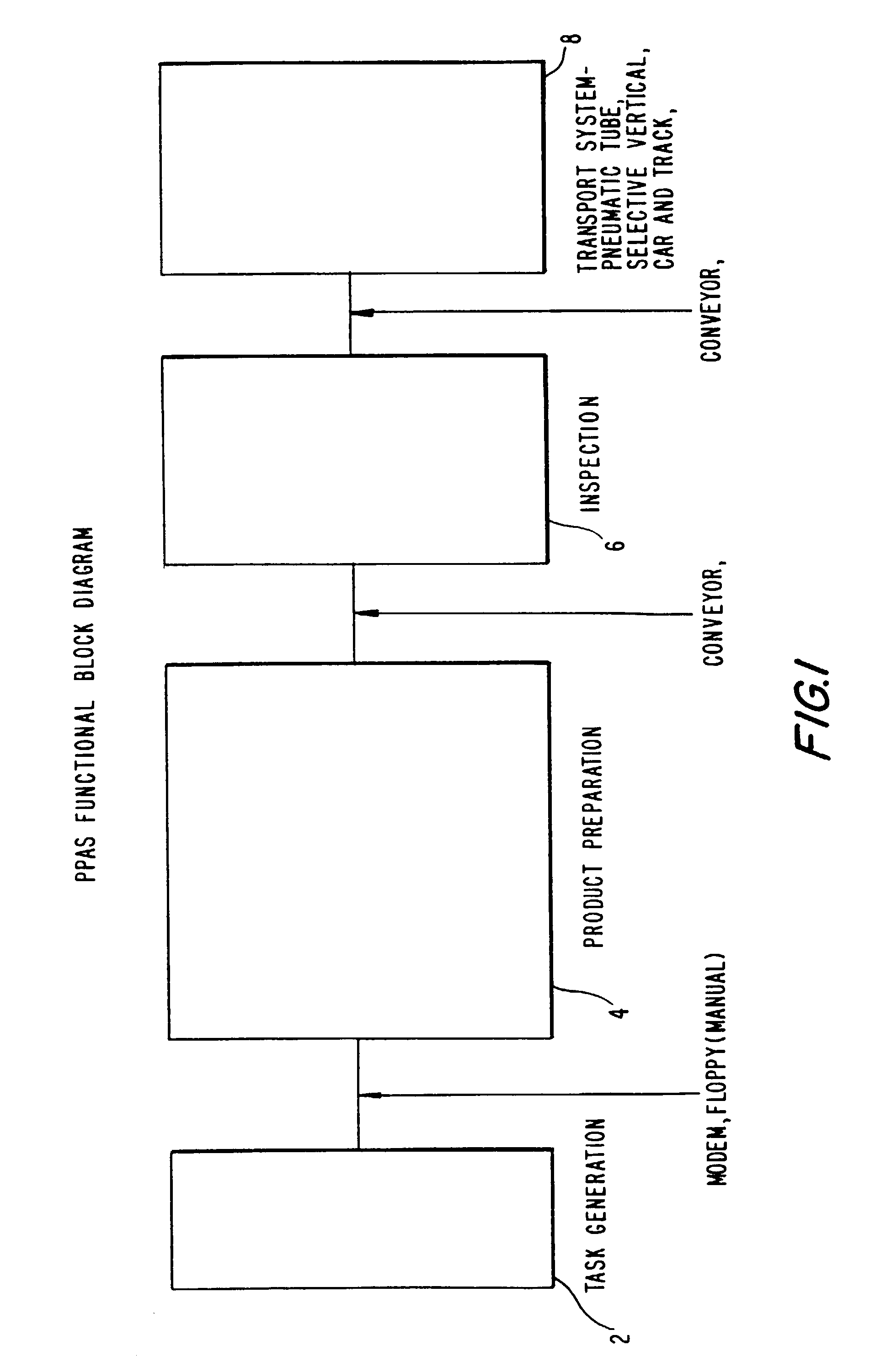
[0077]Referring now to FIG. 1, an overview of the entire present invention is demonstrated in a functional block diagram. It shows input queue step 2 (or task generation step), product preparation step 4, inspection step 6, and transportation step 8.

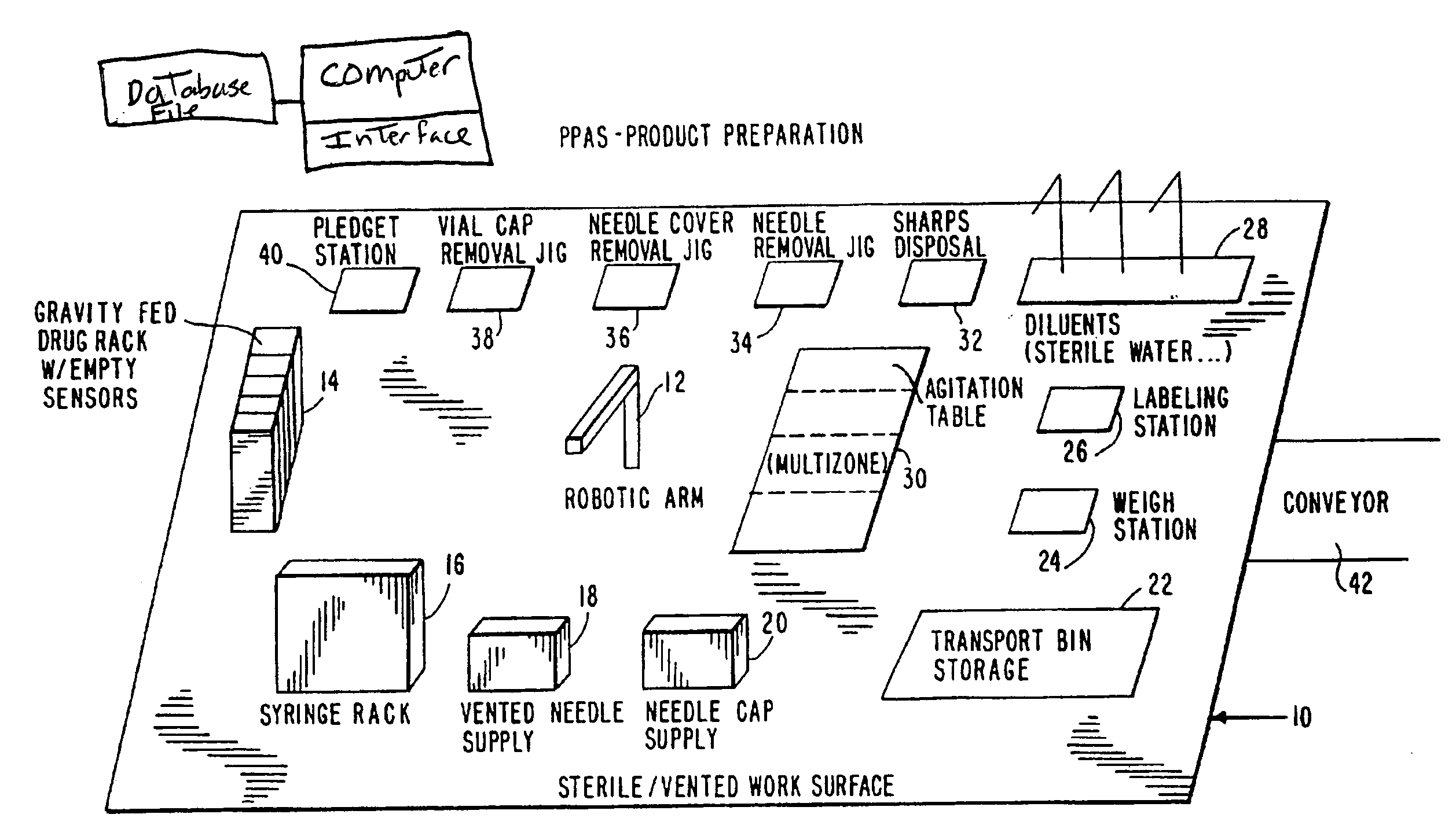
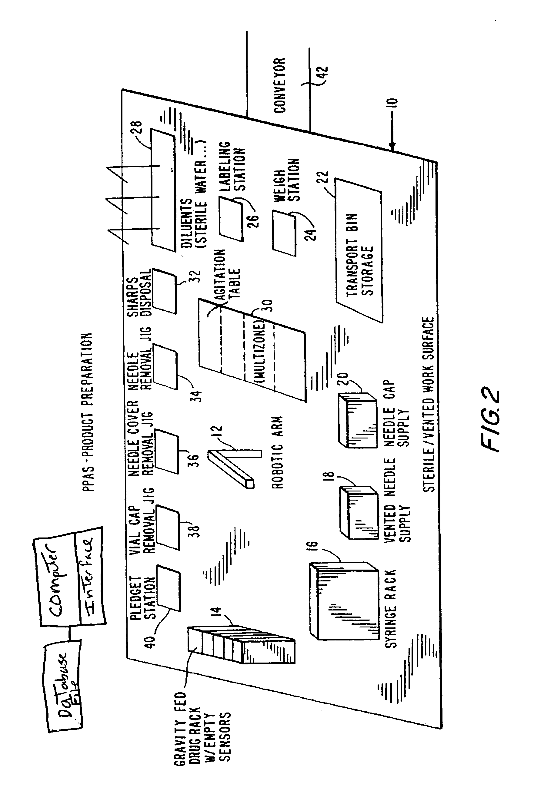
[0078]Referring now to FIG. 2, the product preparation step is shown, and comprises a base 10 having thereon an industrial robot 12 which performs a series of manipulations resulting in the preparation of a single intravenous product unit based upon the information provided by the Pharmacy Information System. The robot 12 may have articulated arms, and gripping means in the form of jaw members having respective depending tangs at a rotatable wrist element of the arm.

[0079]Robot 12 may be arranged to present the jaw members at a number of stations including: gravity fed drug rack 14, syringe rack 16, needle supply rack 18, pledget station 40, vial cap removal jig 38, needle cover removal jig 36, needle removal jig 34, diluents rack 28, mu...


PUM

PropertyMeasurementUnit
Weightaaaaaaaaaa
Timeaaaaaaaaaa
Mechanical propertiesaaaaaaaaaa

Abstract

An integrated, automated system concerning pharmaceutical products is provided. The system comprises an input queue, a dispensing apparatus comprising a robot device and a number of stations from which the robot device works, and an inspection station. A computer interface provides bi-directional communication between the analytical instruments, robots and peripheral devices and a computer. The robot employed by the system is responsive to computer commands and capable of performing mechanical functions including selection and retrieval of a necessary item and manipulation of retrieved items such that the desired product is produced.

Description

CROSS-REFERENCE TO RELATED APPLICATIONS[0001]This application is a continuation of U.S. patent application Ser. No. 09 / 136,786, filed Aug. 19, 1998, (now abandoned), which is a continuation of U.S. patent application Ser. No. 08 / 513,569, filed Aug. 10, 1995, (now issued as U.S. Pat. No. 5,805,454). both of which are incorporated by reference in their entirety.TECHNICAL FIELD[0002]The present invention relates to an automated system for the preparation and delivery of parenteral products from a hospital pharmacy, dietary, laboratory, or central supply to a variety of predetermined stations within a hospital robot devices and a computer interface that integrates the various stations and the components at each station (e.g., analytical instruments, etc.). The system generally comprises a multi-step process including the following: a queue input step; a product preparation step and a product inspection step at which the product is inspected and if the product satisfies all specification...

Claims


Application Information

Patent Timeline
IPC IPC(8): G06F19/00A61J3/00A61J7/00B65G51/34B65G51/46G16H20/13
CPCB01F11/0005B01F13/1072G06Q50/22B65G51/46B65G51/34B65B57/00B65B3/003G16H20/13B01F31/20B01F33/85
Inventor OSBORNE, JOEL A.
Owner BAXTER ENGLEWOOD
Learn More