
Aluminum-silicon alloy having reduced microporosity and method for casting the same

a technology of aluminum-silicon alloy and microporosity, which is applied in the field of aluminum-silicon alloy having reduced microporosity and casting method, can solve the problems of reducing the ductility of the alloy, restricting the flow of eutectic liquid, and difficult to obtain a fine cast microstructure, etc., and achieves high ductility, low cost, and high strength.

Inactive Publication Date: 2008-03-25
BRUNSWICK CORPORATION
View PDF19 Cites 18 Cited by
  • Summary
  • Abstract
  • Description
  • Claims
  • Application Information

AI Technical Summary

Benefits of technology

The patent text describes an aluminum alloy for use in a lost foam casting process that has high strength and ductility, while also being cost-effective. The alloy avoids the addition of iron, which can decrease ductility and cause microporosity. The alloy also has a wider solidification range, which allows for better cast microstructure and prevents leakage under O-ring seals and improves wear resistance. The technical effects of the alloy include improved mechanical properties and reduced microporosity, which makes it suitable for use in applications where high mechanical properties are required.

Problems solved by technology

However, the addition of Mg also decreases the ductility of the alloy.
However, as the molten cast object continues to solidify, the moving molten metal stretches and breaks the spinel, exposing fresh aluminum that solders with the metal die.
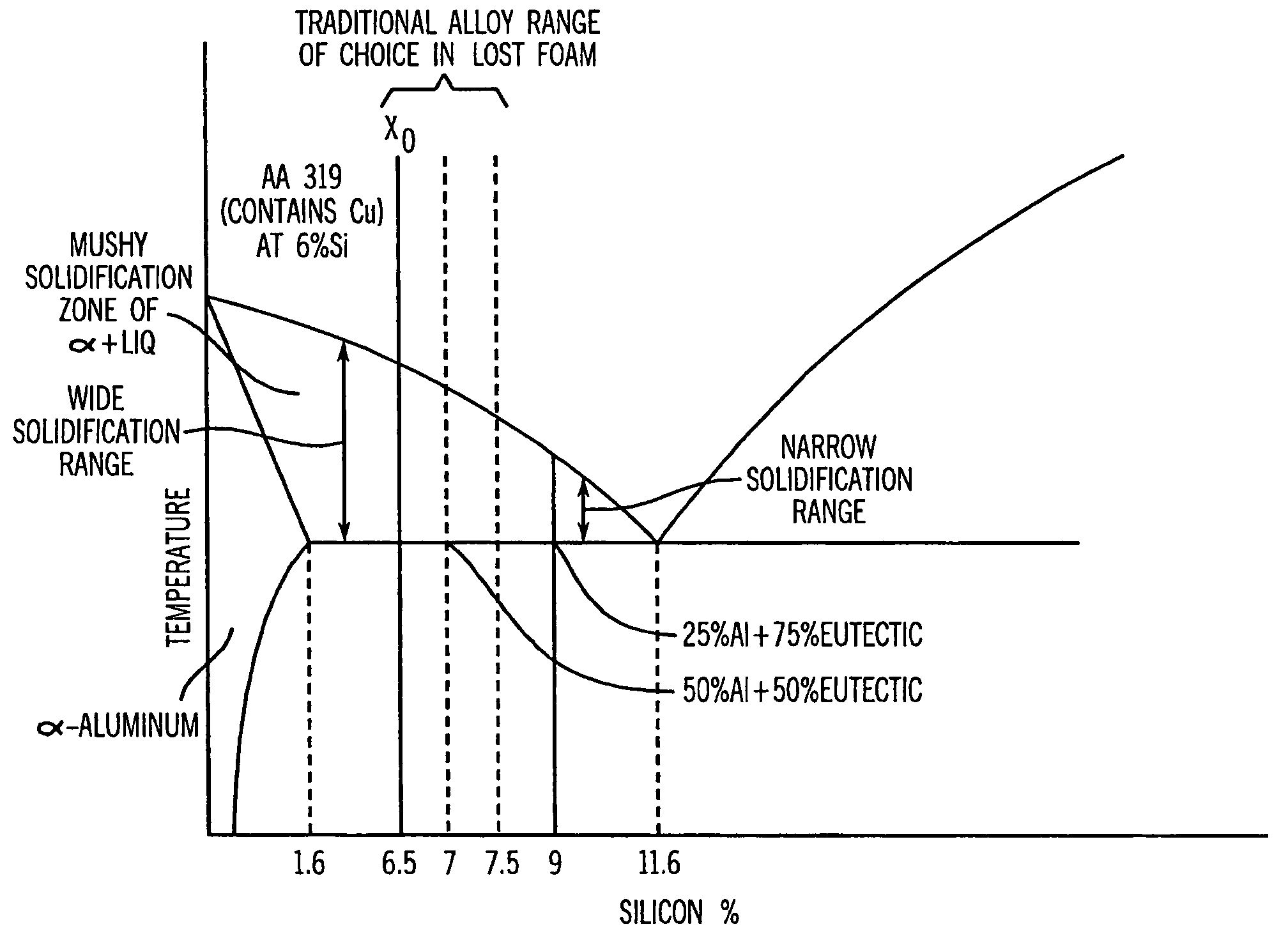
During this time frame, and sometimes even before the precipitation of the primary aluminum phase, the elongated iron needle-like phase also forms and tends to clog the narrow passageways of the aluminum dendritic network, restricting the flow of eutectic liquid.
This occurs because it is difficult to obtain a fine cast microstructure at very slow feeding rates, and because of the increased tendency for castings to be less sound if they freeze thoroughly, particularly if hydrogen porosity is not suppressed.
A high degree of microporosity is undesirable, particularly when the alloy is used for engine blocks, because high microporosity causes leakage under O-ring seals on machined head deck surfaces, and lowers the torque carrying capacity of machined threads.
Similarly, AlSi alloys cast using a high pressure die casting method also result in a porous surface structure due to microporosity in the parent bore material that, if used in engine parts, is particularly detrimental because it contributes to high oil consumption.
Furthermore, microporosity in mechanical parts is detrimental because the microporosity decreases the overall ductility of the alloy.
However, the iron addition degrades mechanical properties, particularly the ductility of the alloy, and to a greater extent than any of the commercial alloying elements used with aluminum.
As a result, die cast alloys are generally not recommended in an application where an alloy having high mechanical properties is required.
Such applications that cannot traditionally be satisfied by the die casting process may be satisfied with much more expensive processes including the permanent mold casting process and the sand casting process.
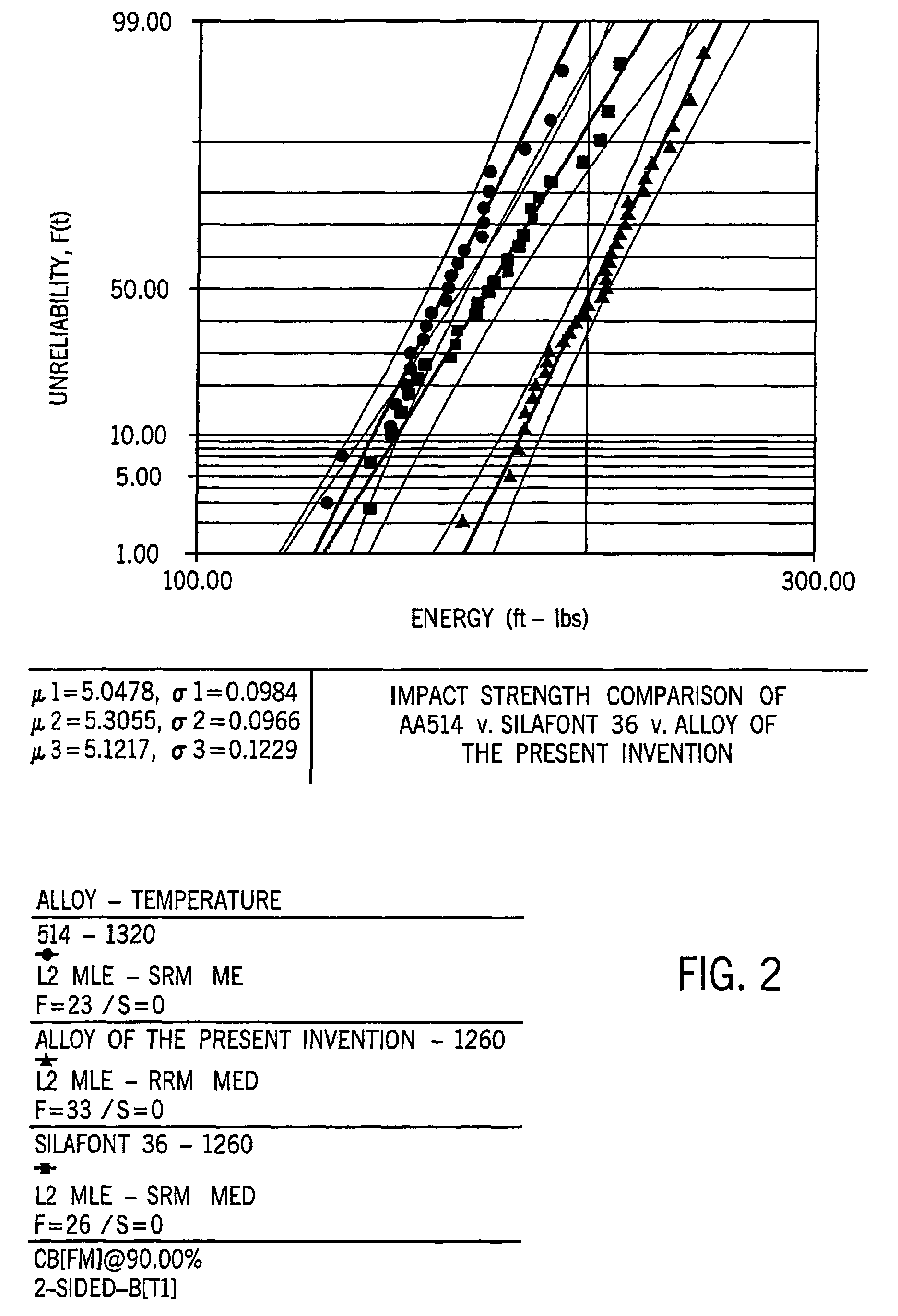
Additionally, AlSi alloys, and particularly hypoeutectic AlSi alloys, generally have poor ductility because of the large irregular shape of the acicular eutectic silicon phase, and because of the presence of the beta-(Fe, Al, Si) type needle-like phase.
The aforementioned iron needles and acicular eutectic silicon clog the interdendritic passageway between the primary aluminum dendrites and hinder feeding late in the solidification event resulting in microporosity (as aforementioned) and also decrease mechanical properties such as ductility.
However, the '514 patent indicates that the same process could not be used with a hypereutectic AlSi alloy modified with P and Na or Sr, because the Na and Sr neutralize the phosphorous effect, and the iron content of the alloy still causes precipitation of the iron phase that hinders interdendritic feeding.
. . ductility cannot be achieved with conventional casting alloys because of high residual Fe content.
During use, outboard marine propellers sometimes collide with underwater objects that damage the propellers.
If the alloy that forms the propeller has low ductility, a propeller blade may fracture off if it collides with an underwater object of substantial size.
High pressure die cast hypoeutectic AlSi alloys have seen limited use for marine propellers because they are brittle and lack ductility.
However, the repairability of such aluminum magnesium propellers is limited.
Thus, AlSi alloys containing magnesium are less desirable than the traditional aluminum magnesium alloys for propellers.
Still, it has been found that aluminum magnesium alloys are significantly more expensive to die cast into propellers because the casting temperature is significantly higher and because the scrap rate is much greater.
Propellers may also be cast using a more expensive semi-solid metal (SSM) casting process.
However, the viscosity is higher and the injection speed is much lower than in conventional pressure die casting, resulting in little or no turbulence during die filling.
Regardless of how marine propellers are cast, the propellers regularly fracture large segments of the propeller blades when they collide with underwater objects during operation.
This is due to the brittleness of traditional propeller alloys, as discussed, above.
As a result, the damaged propeller blades cannot be easily repaired as the missing segments are lost at the bottom of the body of water where the propeller was operated.
Furthermore, the brittleness inherent in traditional die cast AlSi alloys prevents efficient restructuring of the propellers through hammering.
When the boat is traveling at high speeds, a safety concern is present if the lower unit collides with an underwater object.
In this case, the swivel bracket and / or drive shaft housing may fail and allow the outboard assembly with its spinning propeller to enter the boat and cause serious injury to the boat's operator.
Further, as the outboard assembly becomes more massive, this requirement becomes more difficult to meet.
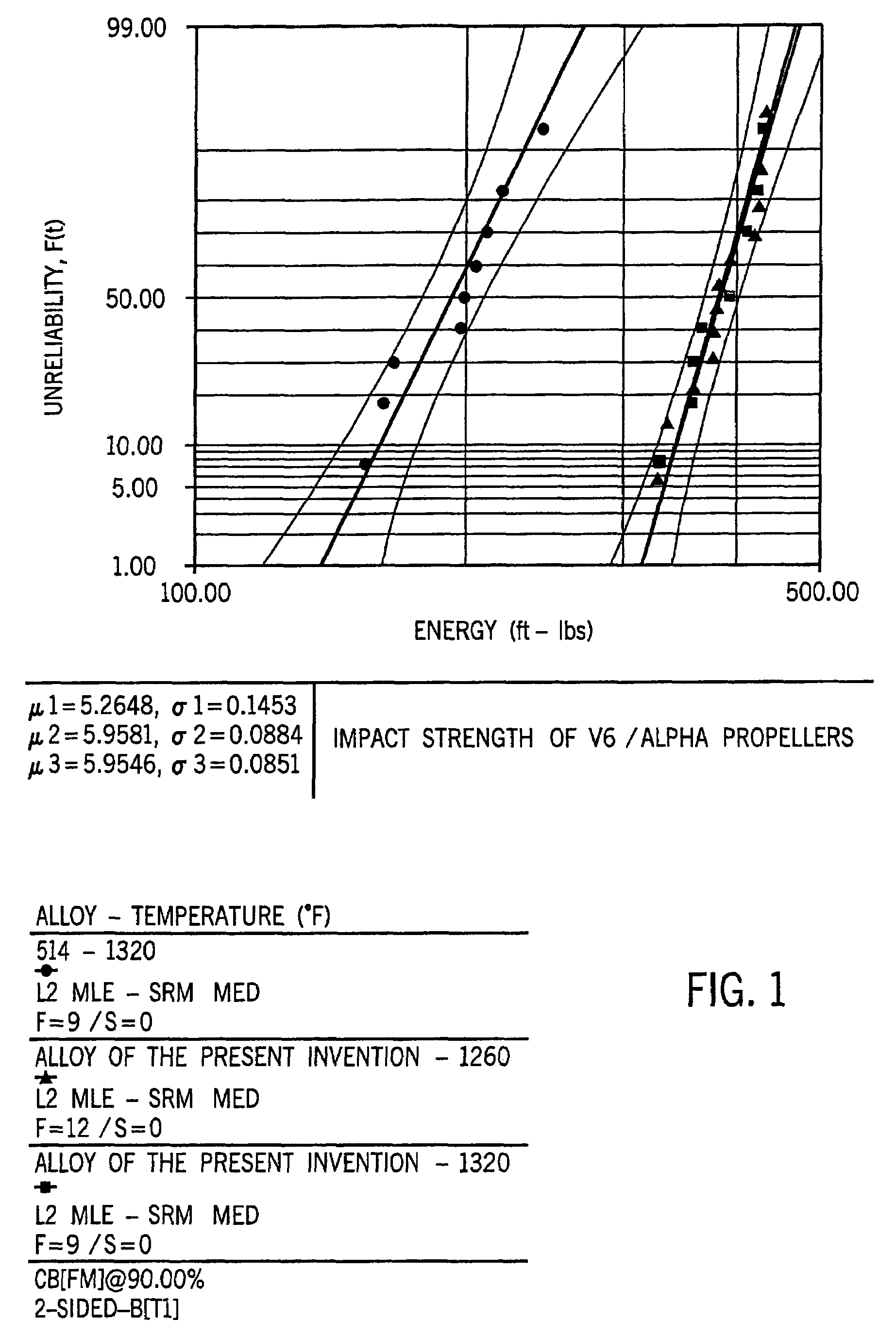
As a result, it is generally accepted that outboards having more than 225 HP have problems meeting industry requirements particularly if the drive shaft housings are die cast because of the low ductility and impact strengths associated with conventional die cast AlSi alloys.
However, parts manufactured using lost foam casting processes are traditionally brittle parts (such as blocks and heads) and has not been used to make damage tolerant, high impact resistant parts.
The skin tends to fracture because of internal liquid tension build-up, causing air to be pulled into the internal, liquid portion of the just cast product, leaving highly undesirable surface-connected porosity.
However, even when AA 356 is cast using the advantageous method of U.S. Pat. No. 6,883,580, a substantial amount of misruns occur because of the relatively low heat of fusion of AA 356 to combat premature freezing from heat extraction during ablation of the foam pattern and gating system.
Further, products cast with AA 356 have a significant amount of surface porosity and require restoration by spray welding.

Method used


Image

  • Aluminum-silicon alloy having reduced microporosity and method for casting the same
  • Aluminum-silicon alloy having reduced microporosity and method for casting the same
  • Aluminum-silicon alloy having reduced microporosity and method for casting the same

Examples


example 1

[0106]An alloy was prepared having the following composition in weight percent: 11.1% silicon, 0.61% magnesium, 0.85% iron, 0.09% copper, 0.22% manganese, 0.16% titanium, 0.055% strontium and the balance aluminum. Thirty-six four-cylinder die cast engine blocks were then produced from this alloy.

[0107]A control lot was prepared using an alloy having the following composition in weight percentage: 11.1% silicon, 0.61% magnesium, 0.85% iron, 0.09% copper, 0.22% manganese, 0.16% titanium and the balance aluminum. Significantly, no strontium was added to this alloy. Thirty-eight four-cylinder blocks were die cast under identical conditions as the blocks of the first alloy using a 1200 ton die casting machine. The only difference between the two sets of blocks is that the first set contained 0.055% by weight strontium and the control lot contained no strontium.

[0108]The control lot and the strontium-containing lot were machined and all machined surfaces, threaded holes and dowel pin hole...

example 2

[0112]An alloy was preparing having the following composition in weight percent: 10.9% silicon, 0.63% magnesium, 0.87% iron, 0.08% copper, 0.24% manganese, 0.14% titanium, 0.060% strontium, and the balance aluminum. Forty 2.5 L V-6, two stroke engine blocks were prepared from this alloy.

[0113]A control lot was prepared using an alloy having the following composition in weight percentage: 10.9% silicon, 0.63% magnesium, 0.87% iron, 0.08% copper, 0.24% manganese. 0.14% titanium and the balance aluminum. Significantly, no strontium was added to this alloy. Thirty-three 2.5 L V-6, two stroke engine blocks were prepared from this alloy.

[0114]Both lots were die cast under identical conditions using a 2500 ton die casting machine, at the same time, and were sequentially numbered. The only difference between the two lots is that the first lot contained 0.060% by weight strontium while the control lot contained no strontium. Both lots were machined together.

[0115]The head decks of the engine...

example 3

[0118]An alloy was prepared having the following composition in weight %:11.3% silicon, 0.63% magnesium, 0.81% iron, 0.10% copper, 0.25% manganese, 0.11% titanium, 0.064% strontium, and the balance aluminum. Thirty-seven 2 L, 4 stroke engine blocks were prepared from this alloy.

[0119]A control lot was prepared using an alloy having the following composition in weight percentage: 11.3% silicon, 0.63% magnesium, 0.81% iron, 0.10% copper, 0.25% manganese, 0.11% titanium, and the balance aluminum. Significantly, no strontium was added to this alloy. Twenty-five 2 L, 4 stroke engine blocks were prepared from this alloy.

[0120]Both lots were die cast under identical conditions using a different die casting machine than the first two examples. The lots were cast at the same time, and were sequentially numbered. The only difference between the two lots is that the first lot contained 0.064% by weight strontium, while the control lot contained no strontium.

[0121]The head decks of the engine b...


PUM

PropertyMeasurementUnit
tensile strengthaaaaaaaaaa

Abstract

An aluminum-silicon lost foam casting alloy having reduced microporosity and a method for casting the same is herein disclosed. A preferred lost foam cast alloy consists essentially of 6 to 12% by weight silicon and preferably 9.0 to 9.5% by weight silicon, 0.035-0.30% strontium, 0.40% maximum iron, 0.45% maximum copper, 0.49% maximum manganese, 0.60% maximum magnesium, 3.0% maximum zinc, and the balance aluminum. Most preferably, the lost foam alloy is free from iron, titanium and boron. However, such elements may exist at trace levels. Most preferably, the alloy is lost foam cast with the process that applies at least 10 atmospheres of pressure during solidification. However, the range may be 5 to 60 atmospheres. The strontium addition is greater than 0.005% by weight and most preferably greater than 0.05% by weight. In accordance with the present disclosure, alloys having substantially decreased tensile liquid failure defects and substantially decreased surface puncture defects in comparison to conventional lost foam cast aluminum silicon alloys are obtained. Further, hydrogen porosity formation is substantially completely suppressed and surface porosity defects are substantially decreased in comparison to conventional lost foam silicon alloys when casting lost foam cast alloys in accordance with the claims of the instant disclosure. The instant disclosure further discloses aluminum silicon alloys that may be utilized in both the lost foam with pressure and the die casting processes.

Description

CROSS-REFERENCE TO RELATED APPLICATIONS[0001]The present application is a continuation-in-part of U.S. application Ser. No. 10 / 429,098 filed May 2, 2003 now U.S. Pat. No. 6,923,935.STATEMENT REGARDING FEDERALLY SPONSORED RESEARCH OR DEVELOPMENT[0002]Not ApplicableINCORPORATION-BY-REFERENCE OF MATERIAL SUBMITTED ON A COMPACT DISC[0003]Not ApplicableBACKGROUND AND SUMMARY[0004]Aluminum silicon (AlSi) alloys are well known in the casting industry. Metallurgists are constantly searching for AlSi alloys having high strength and high ductility and that can be used to cast various parts at a relatively low cost. Herein is described an AlSi alloy for use in a lost foam casting process and a method for utilizing the same.[0005]Most AlSi die casting alloys contain magnesium (Mg) to increase the strength of the alloy. However, the addition of Mg also decreases the ductility of the alloy. Further, during the die casting solidification process, Mg-containing AlSi alloys experience a surface film...

Claims


Application Information

Patent Timeline
Patent Type & Authority Patents(United States)
IPC IPC(8): C22C21/04C22C21/02
CPCC22C21/02C22C21/04
Inventor DONAHUE, RAYMOND J.CLEARY, TERRANCE M.ANDERSON, KEVIN R.
Owner BRUNSWICK CORPORATION
Learn More