Multilayer device for tissue engineering

a tissue engineering and multi-layer technology, applied in the field of tissue engineering, can solve the problems of mass transport, hypoxia and nutrient deprivation, and the limitation of the prior art methods of tissue engineering, and achieve the effects of significant cell death of cells in constructs larger than 1-2 mm

Inactive Publication Date: 2008-05-13
CHARLES STARK DRAPER LABORATORY
View PDF17 Cites 107 Cited by
  • Summary
  • Abstract
  • Description
  • Claims
  • Application Information

AI Technical Summary

Benefits of technology

[0087]We have produced silicon scaffolds plasma-etched using processes that provide acceptable channel widening and near-perfect rounded c

Problems solved by technology

A limitation of the prior art methods of tissue engineering is related to mass transport.
Tissue engineered constructs without a blood supply leads to hypoxia and nutrient deprivation.
Without vasculatu

Method used


Image

  • Multilayer device for tissue engineering
  • Multilayer device for tissue engineering
  • Multilayer device for tissue engineering

Examples


example 1

Silicon Micromachining to Tissue Engineer Branched Vascular Channels for Liver Fabrication

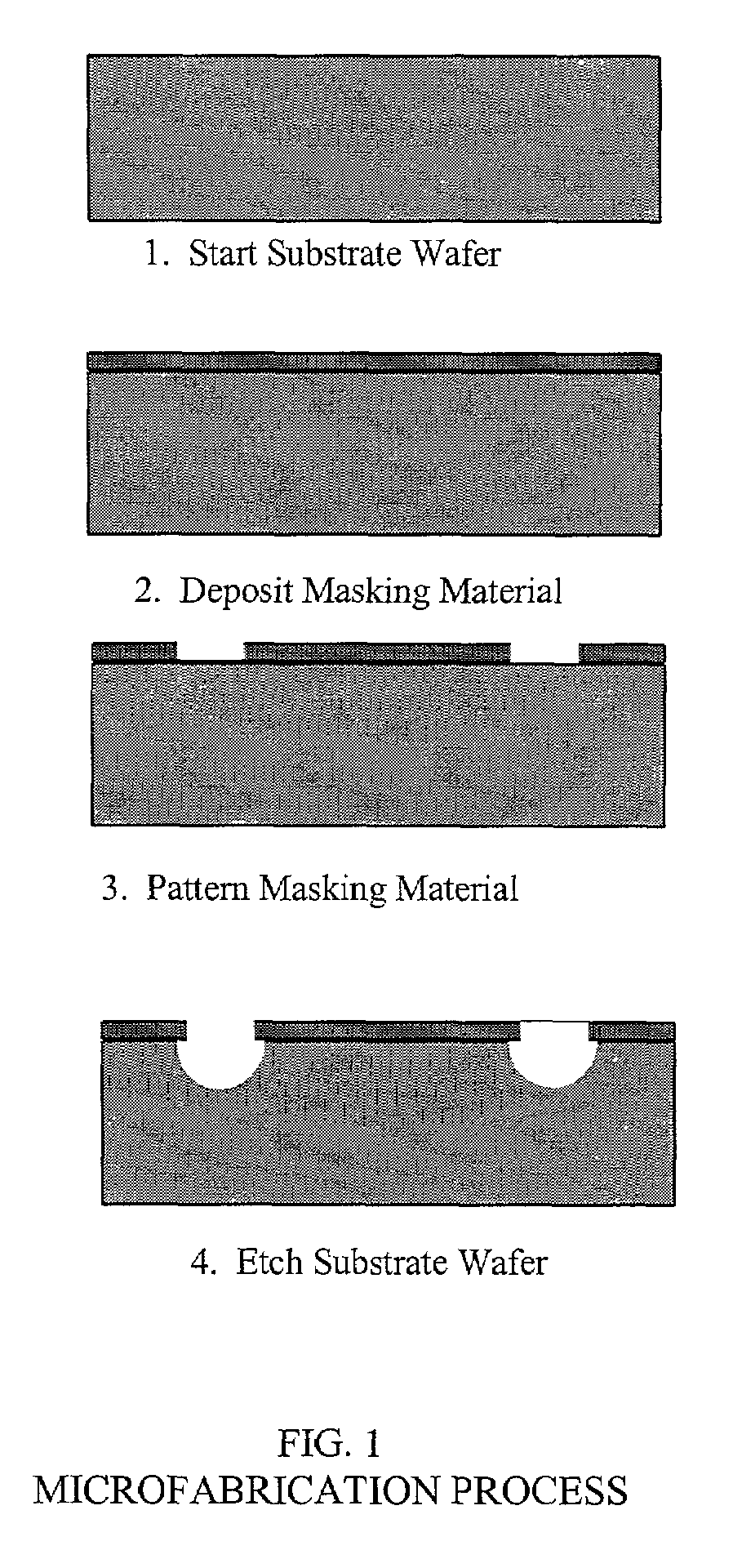
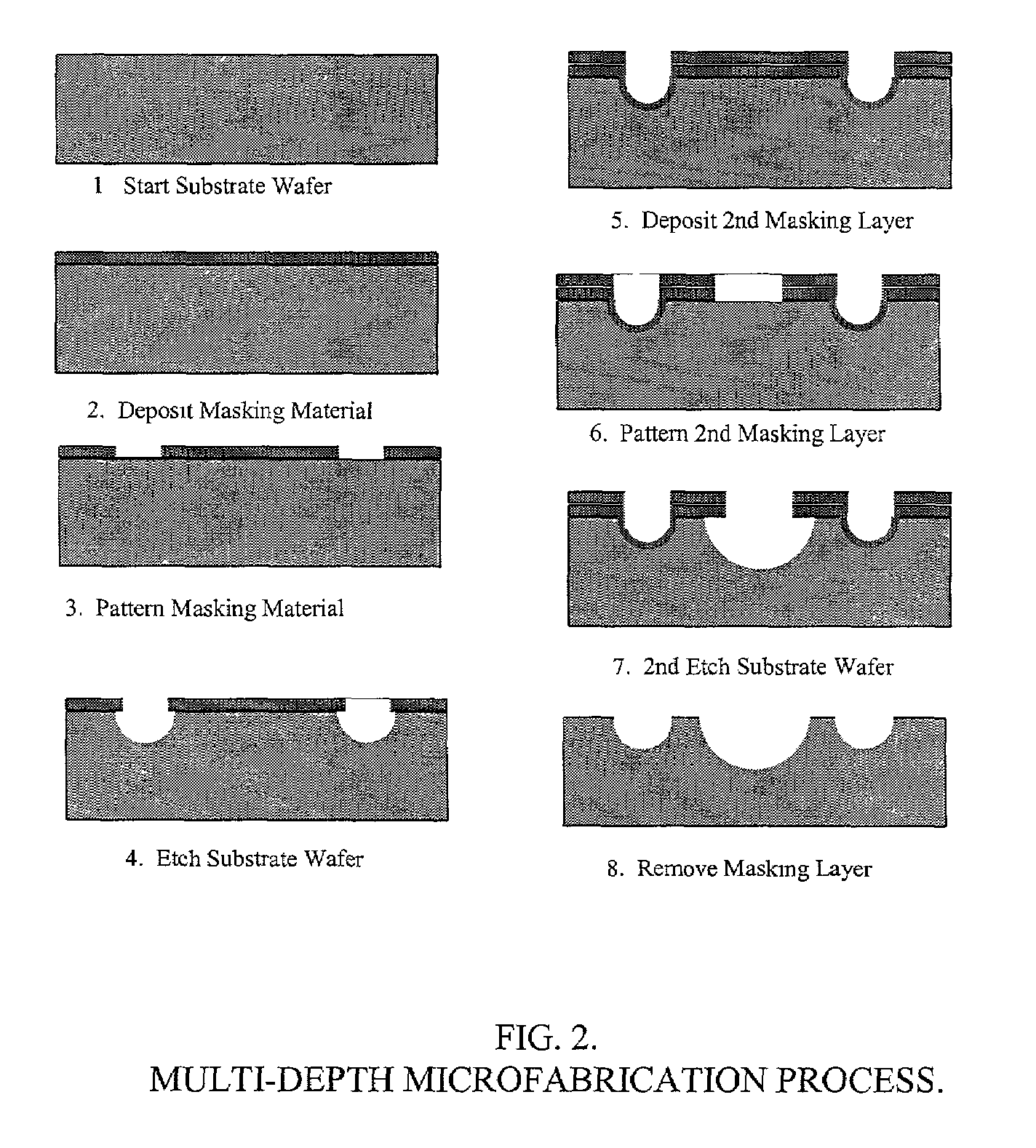
[0154]Templates for the formation of sheets of living vascularized tissue were fabricated using micromachining technology. For this EXAMPLE, a single level etch was used to transfer a vascular network pattern into an array of connected trenches in the surface of either or silicon and glass wafers.

[0155]Micromachining Techniques. A simple geometry was selected for patterning the vascular network. Near the edge of each wafer, a single inlet or outlet was positioned, with a width of 500 μm. After a short length, the inlet and outlet branched into three smaller channels of width 250 μm; each of these branched again into three 125 μm channels, and finally down to three 50 μm channels. From the 50 μm channels extends the capillary network, which comprises the bulk of the layout. Between these inlet and outlet networks lies a tiled pattern of diamonds and hexagons forming a capillary bed and filling t...

example 2

Endothelialized Microvascular Networks Grown on Micromachined PYREX® Templates for Tissue Engineering of Vital Organs

[0184]This EXAMPLE shows the design, modeling, and experimental / computational testing of the endothelialized microvascular matrices grown on micromachined Pyrex® templates.

[0185]Patterns of microvascular networks were etched using microfabrication technologies on Pyrex® wafers. The pattern consisted of 10 generations of bifurcations from a single inflow channel of width 3 mm down to channels of width of 30 microns.

[0186]The channels were then collected to a single outflow. All channels were etched to the same depth of 30 microns. The Pyrex® wafer was sealed to a flat silicone rubber sheet of the same size. Endothelial cells harvested from rat lung were successfully seeded and expanded under continuous flow conditions in this microvascular network. Red blood cells harvested from rat were heparinized and perfused into the endothelialized channels, and successfully colle...

example 3

Microfluidics Device for Tissue Engineering Microvasculature: Endothelial Cell Culture

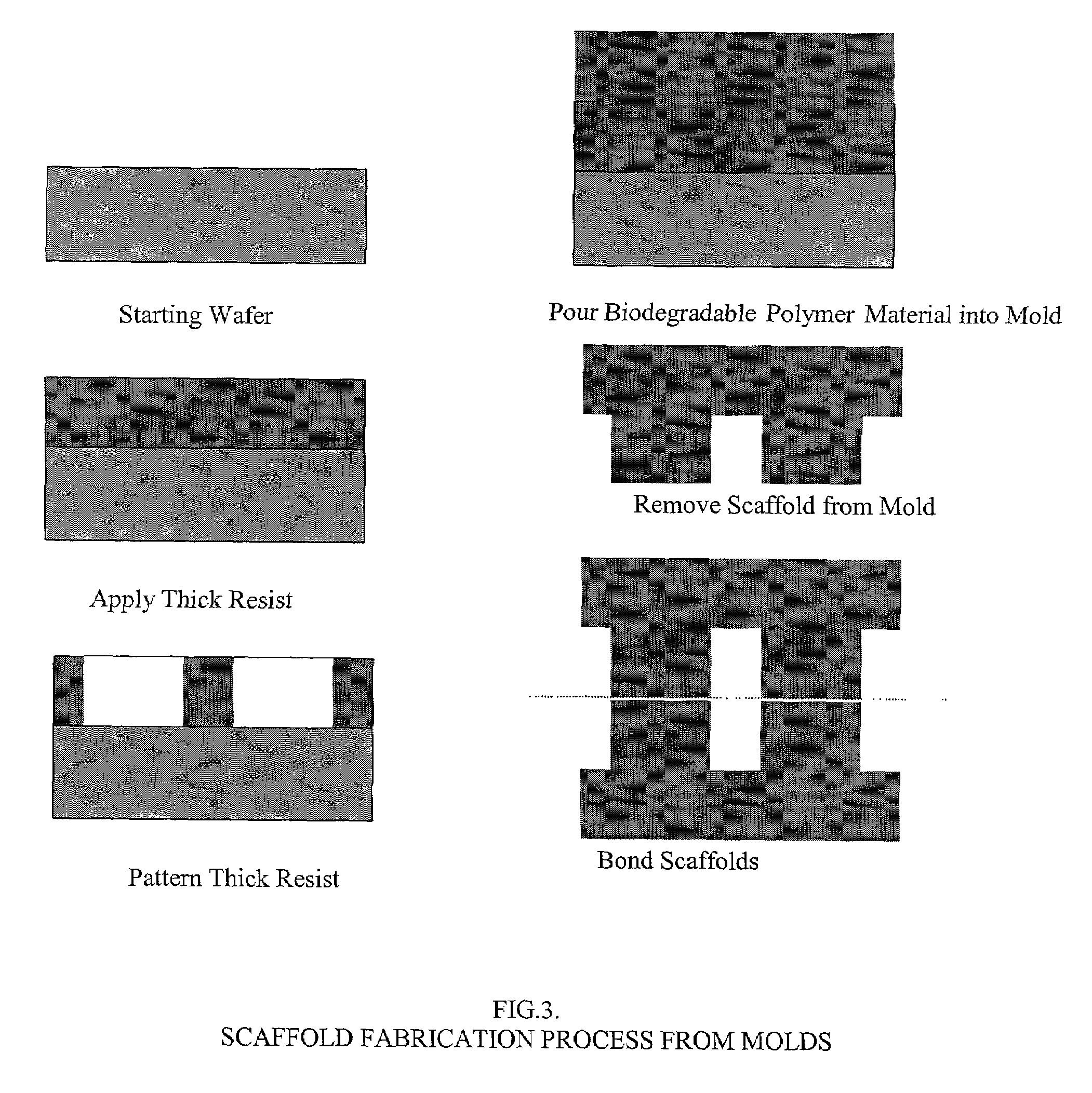
[0190]In this EXAMPLE, we have focused on fabrication of the microfluidic scaffold, in vitro seeding, and extended cell culture in the device. Capillary networks were fabricated in biocompatible PDMS, sterilized, coated with cell adhesion molecules, and seeded with cells. Cell-containing devices were then connected to a closed-loop bioreactor for long-term culture. We have used the device to demonstrate continuous-flow culture of endothelial cells for up to 4 weeks without occlusion or contamination.

[0191]In this EXAMPLE using confined geometries, we used traditional soft lithography microfluidics as a prototype matrix. These cell-containing microfluidics is capable of supporting long-term culture in vitro, because in vitro expansion of cells prior to implantation can take weeks. The prototype matrix is designed to supply sufficient oxygen and nutrients while avoiding large shear stresses. The matr...


PUM

PropertyMeasurementUnit
Thicknessaaaaaaaaaa
Lengthaaaaaaaaaa
Widthaaaaaaaaaa

Abstract

The invention provides for translating two-dimensional microfabrication technology into the third dimension. Two-dimensional templates are fabricated using high-resolution molding processes. These templates are then bonded to form three-dimensional scaffold structures with closed lumens. The scaffolds can serve as the template for cell adhesion and growth by cells that are added to the scaffolds through the vessels, holes or pores. These scaffolds can be formed by layering techniques, to interconnect flat template sheets to build up a fully vascularized organ.

Description

CLAIM OF PRIORITY[0001]This application claims priority to U.S. provisional patent application Ser. No. 60 / 259,283; filed Jan. 2, 2001.GOVERNMENT INTERESTS[0002]Some of the work described herein was sponsored by the Department of the Army, Cooperative Agreement DAMD-99-2-9001. The U.S. Government has certain rights in this invention.FIELD OF THE INVENTION[0003]The invention relates generally to tissue engineering. Specifically, this invention provides a technique for fabricating three-dimensional vascularized tissues for transplantation in human recipients.BACKGROUND OF THE INVENTION[0004]Vital organ failure is one of the most critical problems facing the health care field today. In the United States, the number of patients awaiting an organ for transplant has risen above 75,000. Despite advances in living donor organ transplantation, a severe shortage of donor organs available to these patients remains as the crux of the problem. Mechanical devices are one approach to addressing th...

Claims


Application Information

Patent Timeline
IPC IPC(8): A61F2/00C12N11/02C12N11/08C12N5/06C12N5/08A61F2/02A61F2/06A61K35/12A61L27/38A61L27/56B01L3/00B29C67/00B32B7/02B81B1/00C12N5/00C12N5/071
CPCA61L27/3604A61L27/3804A61L27/3808A61L27/3891A61L27/56B01L3/5027B01L3/502707B29C65/00B29C65/002B29C65/02B29C65/56B29C66/54B29C67/007B29C67/0092B32B7/02C12N5/0068C12N5/0671C12N5/069C12N5/0697C12M21/08C12M23/16A61F2/062A61F2/0077Y10T428/24744A61F2/3094A61F2002/0086A61F2002/30004A61F2002/30062A61F2002/30064A61F2002/30199A61F2002/30925A61F2002/30929A61F2002/3093A61F2002/30957A61F2002/30971A61F2210/0004A61F2230/0063A61F2240/001A61F2240/004A61F2250/0014A61F2310/00179A61F2310/00329A61K35/12B01L2200/12B01L2300/0874B01L2300/163B29C65/4895B29C65/562B29L2031/756C12N2502/14C12N2502/28C12N2533/40C12N2535/10B29C66/5346B29C65/48B29C66/7379B29C66/73791B29C66/71B29C64/129B29C64/40B33Y80/00B29K2001/12B29K2023/00B29K2023/083B29K2025/06B29K2027/06B29K2027/08B29K2027/14B29K2029/04B29K2031/00B29K2033/08B29K2033/12B29K2067/00B29K2067/003B29K2067/043B29K2067/046B29K2069/00B29K2071/02B29K2075/00B29K2077/00B29K2083/00
Inventor BORENSTEIN, JEFFREY T.KING, KEVIN R.TERAI, HIDETOMIVACANTI, JOSEPH P.
Owner CHARLES STARK DRAPER LABORATORY
Why Eureka
Try Eureka