

Electron beam apparatus, a device manufacturing method using the same apparatus, a pattern evaluation method, a device manufacturing method using the same method, and a resist pattern or processed wafer evaluation method
a technology of electron beam and manufacturing method, applied in the direction of individual semiconductor device testing, semiconductor/solid-state device testing/measurement, instruments, etc., can solve the problems of inability to achieve such a single beam beam, inability to achieve such a single beam, and inability to achieve a single beam. , to achieve the effect of reducing and increasing the number of beams
- Summary
- Abstract
- Description
- Claims
- Application Information
AI Technical Summary
Benefits of technology
Problems solved by technology
Method used
Image

Examples
first example
[0313]First, an overview of an electron beam apparatus according to the first invention will be presented.
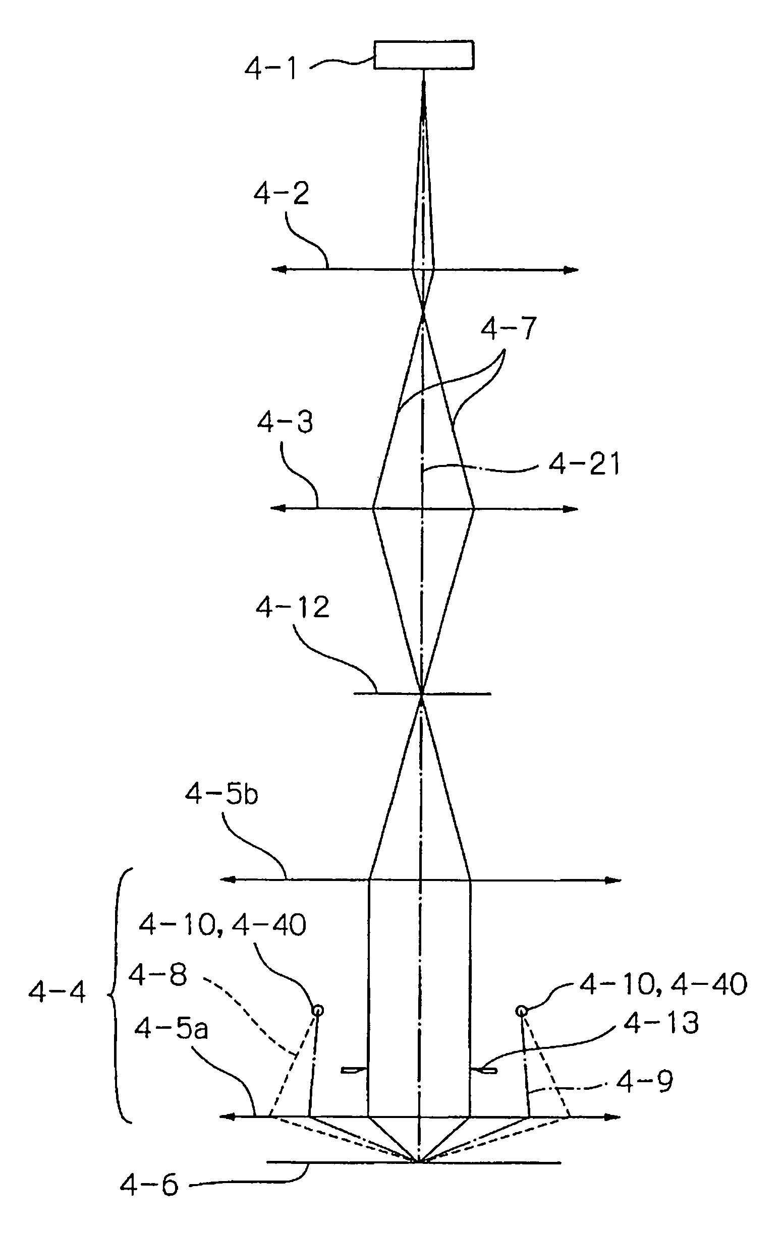
[0314]An electron beam apparatus according to an embodiment of the present invention as shown in FIG. 1 comprises an electron beam emitter section 32 having an electron gun 30, a plurality of apertures 34 disposed at a location out of an optical axis 23 and an electromagnetic lens 7 operable to control an on-axis electron beam and a plurality of off-axis electron beams emitted from the electron gun 30 so that said plurality of off-axis electron beams may pass through the apertures 34.
[0315]The electron beam emitter section 32 comprises two electron guns 30 and a housing 38 serving for holding the electron guns 30 as well as defining an electron gun chamber 5, and an ion pump 6 for evacuating the electron gun chamber 5 to high vacuum is attached to the housing 38. Further, each of the electron guns 30 is connected with a mechanism 28 for activating the electron gun 30 mechanicall...
second example
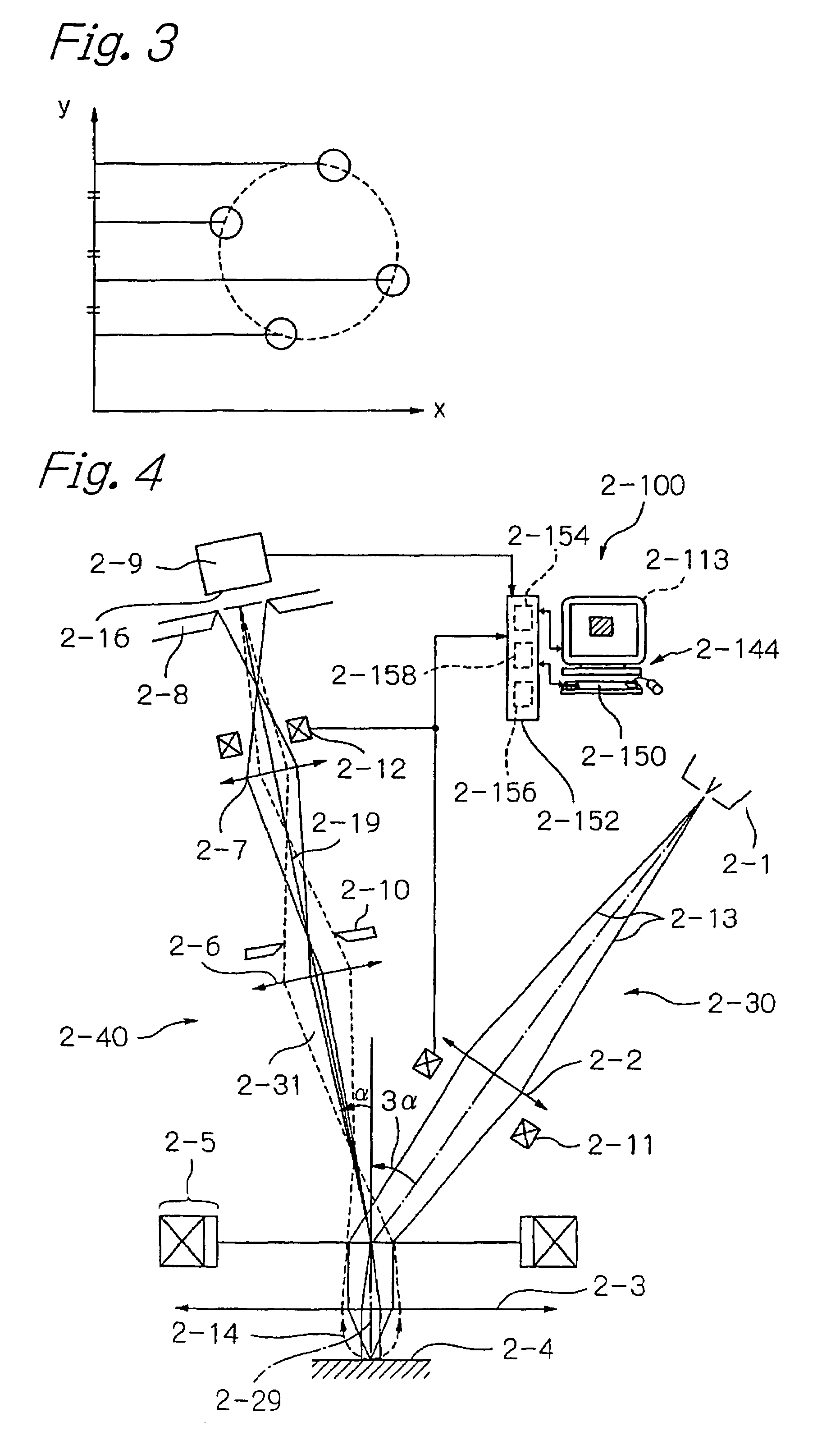
[0328]A first embodiment using a single beam embodying the second invention will now be described with reference to FIG. 4. An electron beam apparatus of this illustrated embodiment comprises an electron gun 2-1 serving as an electron beam source emitting a primary electron beam 2-13, a primary optical system 2-30 for guiding the primary electron beam onto a sample 2-4 to scan said sample 2-4 with the primary electron beam, a secondary electron detecting unit 2-9 having a detection surface 2-16 for detecting a secondary electron beam 2-14 emitting from the sample 2-4, a secondary optical system 2-40 for guiding the secondary electron beam 2-14 emitting from the sample 2-4 to be focused into an image on the detection surface 2-16 of the secondary electron detecting unit 2-9 and a controller 2-100 for controlling the electron beam apparatus.
[0329]The electron gun 2-1 of thermionic beam source type has been employed, in which electrons are emitted by heating an electron emission materi...
third example
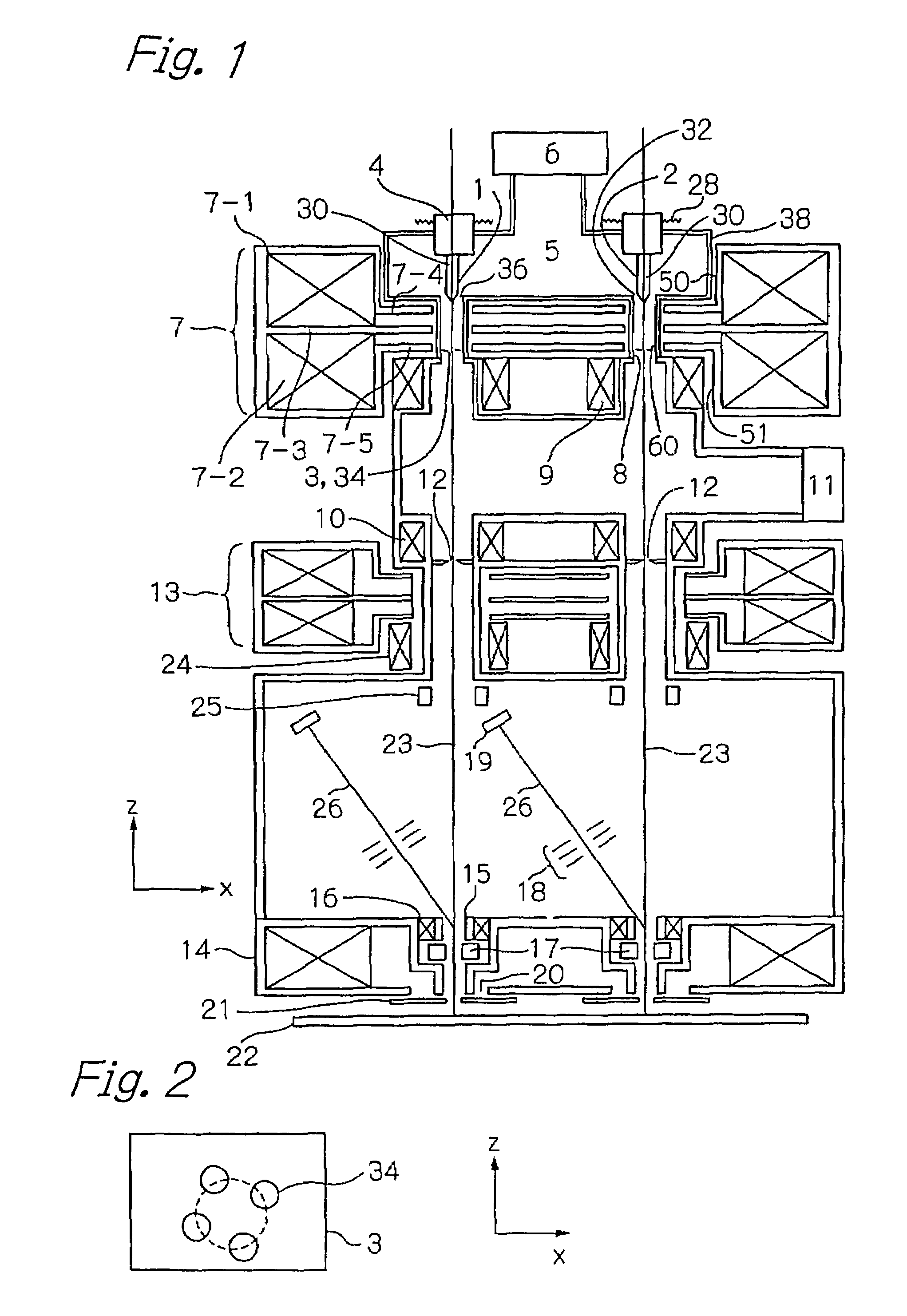
[0350]An electron beam apparatus according to a second embodiment of the second invention will now be described with reference to FIG. 7. FIG. 7 is a schematic view of an electron beam apparatus according to the second embodiment of the present invention, in which a primary electron beam is composed of a multi-beam. This electron beam apparatus, as shown in FIG. 7(a), comprises an electron gun 2-41 serving as an electron beam source for emitting a primary electron beam, a primary optical system 2-42 for guiding the primary electron beam onto a sample 2-53 to scan the sample 2-53 with the primary electron beam, a secondary electron detecting unit 2-59 including a plurality of secondary electron beam detectors provided with detection surfaces 2-61 for detecting a secondary electron beam emanating from the sample 2-53, a secondary optical system 2-54 for guiding the secondary electron beam emitting from the sample 2-53 to be focused into an image on the detection surface 2-61 of the se...
PUM
| Property | Measurement | Unit |
|---|---|---|
| angular current intensity | aaaaa | aaaaa |
| angular current intensity | aaaaa | aaaaa |
| specific angular current intensity | aaaaa | aaaaa |
Abstract
Description
Claims
Application Information