Very large area/volume microwave ECR plasma and ion source

a plasma and microwave ecr technology, applied in the direction of ion beam tubes, coatings, chemical vapor deposition coatings, etc., can solve the problems of plasma non-uniformity, short service life of plasma generators, and limited lifetimes of dc ion sources (and dc electron sources)

Inactive Publication Date: 2009-02-24
ADMINISTATOR OF NAT AERONAUTICS & SPACE ADMINISTATION U S GOVERNMENT AS REPRESENTED BY THE
View PDF16 Cites 22 Cited by
  • Summary
  • Abstract
  • Description
  • Claims
  • Application Information

AI Technical Summary

Problems solved by technology

Drawbacks of existing direct current (DC) ion sources include erosion, short service life of plasma generators, and plasma non-uniformity.
This is an undesirable attribute from the standpoint of materials processing, as contamination of the work product can result.
DC ion sources (and DC electron sources) have limited lifetimes due to being constantly subjected to erosion, and the cathodes that drive such plasma sources typically, over time, lose their ability to emit electrons so that eventually the cathodes fail.
Typically, DC ion sources (ion thrusters in particular) utilize a single on-axis discharge cathode, which gives rise to peaked, non-uniform plasma density profiles at the exit plane.
Such non-uniform profiles cause non-uniform wear of the ion extraction grids—thereby leading to failure by structural degradation or by electron backstreaming.
The insulating window, typically boron nitride makes such devices impractical for ion sources or ion thruster applications because the insulating window acquires over time a coating due to wear of the extraction grids.
Achieving these plasma characteristics is generally difficult from the standpoint of issues such as recombination, collisional losses and diffusion, all of which reduce discharge efficiency and uniformity of the discharged reaction mass.
However, such discharges tend to be of poor uniformity and to introduce erosion products due to cathode degradation (as it is exposed to the discharge plasma and bombarded by high-energy discharge ions).
In this respect, conventional hollow cathode based discharge sources are not a solution to long life and low erosion plasma sources.
In this system, the microwave discharge is fundamentally limited in maximum plasma density, efficiency, and pressure.
It is not an efficient ion source at the kinds of low pressures that are desirable for directional etching and sputter deposition applications in microelectronics.
The invention of Ishii, et al., also uses a dielectric window, which can be problematic for both ion thruster uses and many deposition microelectronics reactors where metal vapor is present in the plasma.
Additionally, the device of Ishii, et al., utilizes a coaxial line connection to the slotted antenna, which limits the amount of power, plasma density and thus the maximum dimension to which the source can be built, thus limiting the ability to scale it up without recourse to a complete system redesign to scale up to a larger size.
In this regard, its size is limited and can be scaled up only with difficulty.
Such devices operated at pressures ˜1 Torr and plasma densities are low and not particularly suited for etching or Sputter deposition.
Sputter contamination is an issue for such a source.
This technology suffers from limitations described above in comments 1-4.
It also presents a lifetime issue as the antenna would be subject to sputtering.
The device is not scalable to larger dimensions of the sort useful for large area plasma processing, high current, or long life ion thruster applications.
Moreover, it is limited with respect to plasma density, which means that a workpiece to be processed must rely on the diffusion of the magnetized plasma, which is in general a slow process and can result in non-uniformities.
And because it has an internal antenna it will be subject to sputter erosion limitations on service life, while also generating contaminants.
The outer ceramic shield would be subject to the formation of metal coatings over time, which could affect the microwave coupling and thus the overall operation.
Also because the device is coaxially fed, it is inherently limited to reduced microwave power.
Additionally, as each internal antenna is coaxially fed, which makes them power limited.
“Plasma Treatment System,” utilizes a coax fed slotted antenna which inherently limits power and complicates implementation, as the coax feed would necessarily be water cooled at modest powers.
Additionally, the slotted antenna geometry of this invention is complicated and its overall layout does not lend well to scaling up in power.
The antenna geometry is sophisticated, thereby imposing or requiring significant fabrication effort.
In this regard, it has to operate at a high background pressures that limit its uses.

Method used


Image

  • Very large area/volume microwave ECR plasma and ion source
  • Very large area/volume microwave ECR plasma and ion source
  • Very large area/volume microwave ECR plasma and ion source

Examples


Embodiment Construction

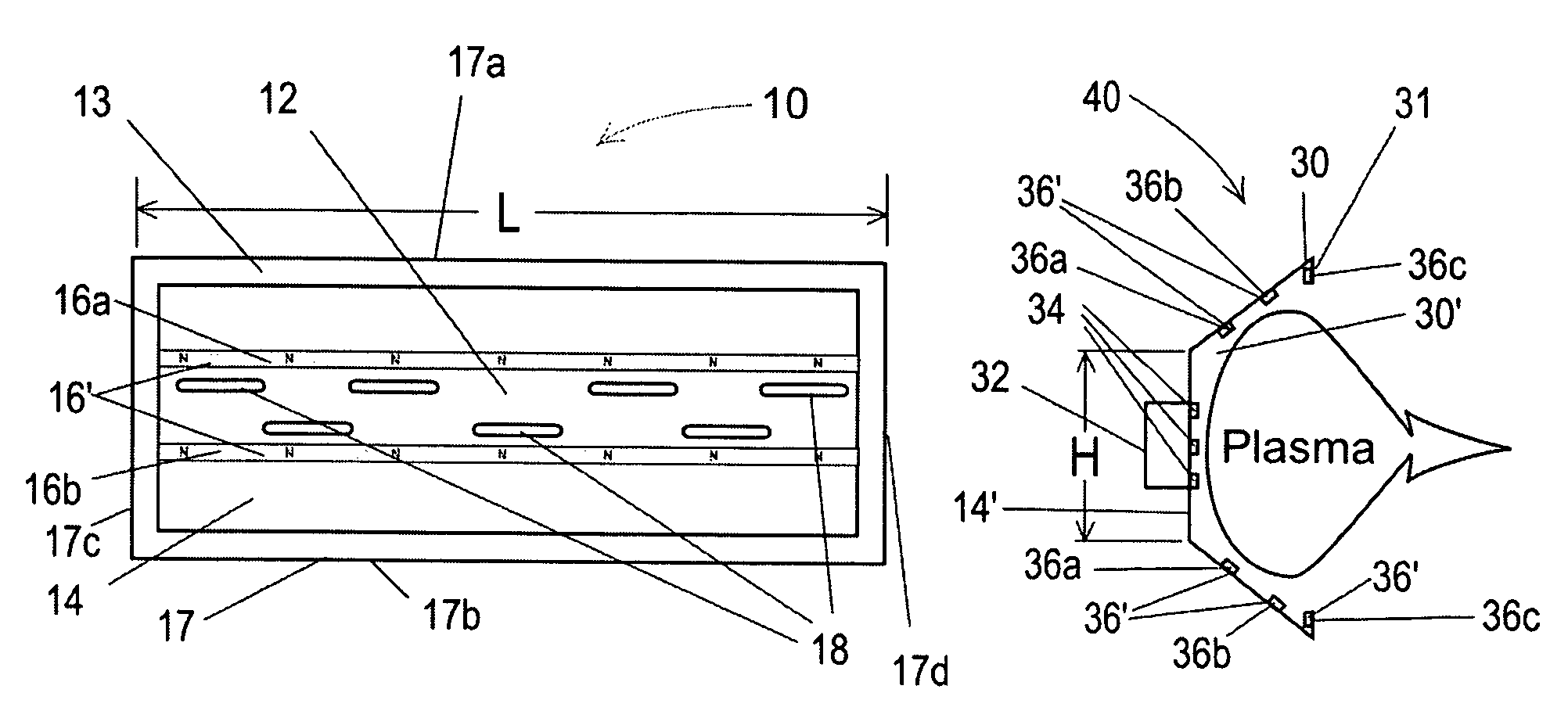
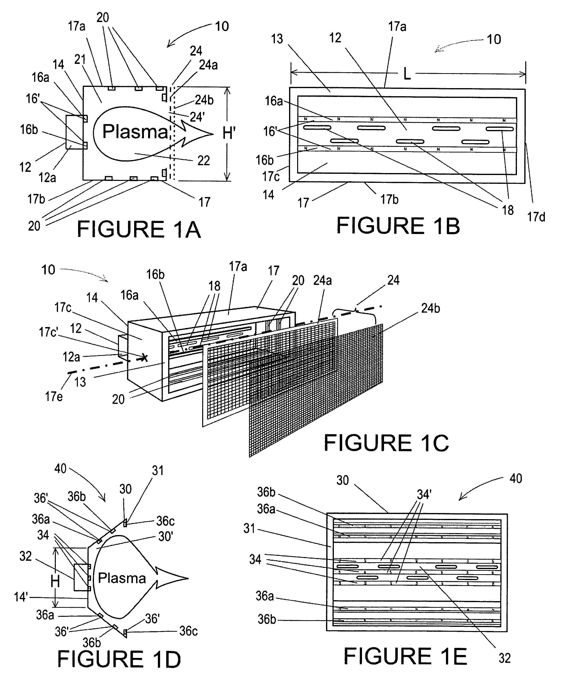
[0042]The present invention is a large area and large volume microwave electron cyclotron resonance (ECR) plasma and ion source that can be used as either a high density, large area plasma source and / or as an ion source. It is electrodeless and windowless. Its applications include materials processing operations such as ion milling and ion implantation and ion propulsion for space vehicles. An analysis of the performance of the present invention, entitled, “High Power ECR Ion Thruster Discharge Characterization,” was presented by the inventor at the International Electric Propulsion Conference on Nov. 2, 2005, and is incorporated herein in its entirety by reference hereto.

[0043]FIG. 1A is an orthogonal, cut-away, schematic end-view of one embodiment 10 of a large area, large volume, plasma and ion source 10 according to the present invention. FIG. 1B is an orthogonal schematic front view of this embodiment of the ion source 10, and FIG. 1C is an oblique view of the ion source 10.

[00...


PUM

PropertyMeasurementUnit
pressuresaaaaaaaaaa
frequencyaaaaaaaaaa
frequencyaaaaaaaaaa

Abstract

The present invention is an apparatus and method for producing very large area and large volume plasmas. The invention utilizes electron cylcotron resonances in conjunction with permanent magnets to produce dense, uniform plasmas for long life ion thruster applications or for plasma processing applications such as etching, deposition, ion milling and ion implantation. The large area source is at least five times larger than the 12-inch wafers being processed to date. Its rectangular shape makes it easier to accommodate to materials processing than sources that are circular in shape. The source itself represents the largest ECR ion source built to date. It is electrodeless and does not utilize electromagnets to generate the ECR magnetic circuit, nor does it make use of windows.

Description

STATEMENT REGARDING FEDERALLY SPONSORED RESEARCH OR DEVELOPMENT[0001]The invention described herein was made by an employee of the United States Government and may be manufactured and used by or for the Government for Government purposes without the payment of any royalties thereon or therefore.RELATED APPLICATIONS[0002]U.S. application Ser. No. 10 / 894,225 entitled LARGE AREA PLASMA SOURCE filed Jul. 19, 2004 by J. Foster.[0003]U.S. application Ser. No. 10 / 925,499 SLOTTED ANTENNA WAVEGUIDE PLASMA SOURCE filed Aug. 25, 2004 by J. Foster.TECHNICAL FIELD OF THE INVENTION[0004]The present invention relates to large area and large volume plasma sources and to microwave antennas used for producing plasmas for use in ion thrusters, ion etching of surfaces, the embedding of ions within surfaces, production of electrons, and the like.BACKGROUND[0005]Plasmas consist of gaseous complexes in which atoms or molecules are dissociated into free electrons, ions, free radicals, and neutral particles...

Claims


Application Information

Patent Timeline
Patent Type & Authority Patents(United States)
IPC IPC(8): C23C16/00
CPCH01J27/18H01J37/32192H01J37/3222H01J37/3266H01J37/32678
Inventor FOSTER, JOHN E.PATTERSON, MICHAEL J.
Owner ADMINISTATOR OF NAT AERONAUTICS & SPACE ADMINISTATION U S GOVERNMENT AS REPRESENTED BY THE
Why Eureka
Try Eureka