
Liquid flow controller and precision dispense apparatus and system

a technology of precision dispense apparatus and liquid flow controller, which is applied in fluid pressure control, process and machine control, instruments, etc., can solve the problems of destroying the pattern formed on the wafer, requiring reprocessing, and requiring reprocessing. , to achieve the effect of reducing operator involvement, accurate and repeatable fluid flow control, and reducing the number of operators

Inactive Publication Date: 2009-06-09
ENTEGRIS INC
View PDF22 Cites 32 Cited by
  • Summary
  • Abstract
  • Description
  • Claims
  • Application Information

AI Technical Summary

Benefits of technology

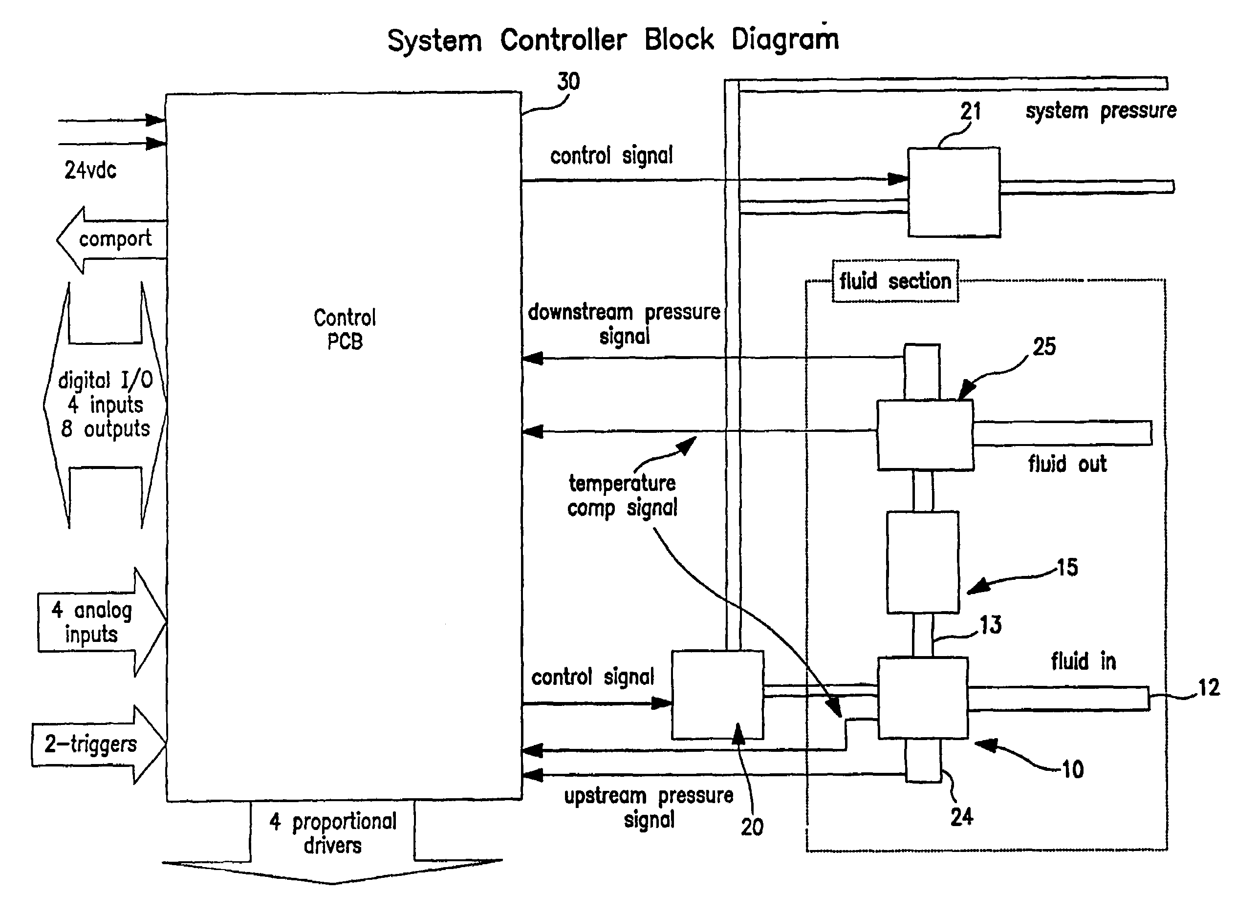
"The present invention provides a system for monitoring and controlling the pressure of a pneumatic load, such as a proportional fluid control valve, using a measurement input from a fluid measurement device that responds to a flow rate. The system can adapt to changes in fluid viscosity and temperature, and can be used in a variety of fluids and motorless pump systems. The system offers accurate and repeatable fluid flow control and dispense performance, responding quickly to real-time process variations with minimum operator involvement. The invention also includes an auxiliary input module upstream of the flow measurement device that can condition fluid prior to being presented to the flow measurement device, and a versatile molded valve body that requires fewer parts compared to a machined valve. The invention further provides a set of computer readable instructions for receiving and calculating an upstream pressure signal, an downstream pressure signal, an error signal, and a valve control signal to modulate the valve's position to achieve the desired flow rate."

Problems solved by technology

This can destroy the pattern being formed on the wafer, requiring that the wafer be discarded or reprocessed.
The coating of larger wafers (e.g., 300 mm in diameter and larger) is also problematic, as turbulence issues arise.
However, this approach creates turbulent airflow over the wafer and can result in uneven or nonuniform coatings.
Reducing the spin speed with larger wafers reduces the turbulence at the surface of the wafer, but can introduce new problems.
With the reduced speed, the fluid moves slower across the wafer, and thus spreading the fluid to the wafer edge before the fluid begins to setup or dry becomes an issue.
However, the pumps suitable for such applications are expensive and require frequent replacement due to excessive wear.
In addition, the footprint of such pumps may be too large to be justified for all but the most demanding applications.
Liquid flow controllers such as the NT 6500 (Entegris Corp., Chaska, Minn.) are available that include differential pressure measurement, but they are not adaptable to a wide range of different flow rates and or viscosities.

Method used


Image

  • Liquid flow controller and precision dispense apparatus and system
  • Liquid flow controller and precision dispense apparatus and system
  • Liquid flow controller and precision dispense apparatus and system

Examples


example 1

[0121]The system was set up so that a known differential pressure and a fixed dispense time could be inputted to the controller, and a dispense could be subsequently triggered from a laptop computer. The resultant output flow of deionized water was captured in a container and weighed using a precision scale to determine its mass. Using the mass of each dispense combined with the known density of the fluid material, the volume of each dispense was calculated. Combining the volume dispensed with the known dispense time resulted in a flow rate determination. Five different viscosities were checked, ranging from about 0.92 to about 9.5 centipoise. The results are shown graphically in FIG. 10.

example 2

[0122]Three different valves were tested for hysteresis, including two commercially available valves, and the valve of the present invention shown in FIGS. 8A-8D. The valve actuation pressure was varied up and down and the pressure inside the test system was measured in steps up and down through the valve actuation pressure range and plotted as voltage. More specifically, the test set-up was a closed system of the valve and downstream pressure sensor, with the valve under constant pressure and the pressure sensor monitoring the change in pressure downstream of the valve as the valve moved through its range of closed to full open and back again to closed.

[0123]The results are shown graphically in FIGS. 9A, 9B and 9C. In each graph, the curve farthest to the right represents the data for varying the pressure from low to high, and the curve to the left is the result of varying pressure from high to low. The difference between the curves represents the amount of hysteresis. Thus, as the...

example 3

[0124]This example illustrates the use of an embodiment of the present invention to measure and control liquid flow to enable the delivery of discrete volumes of fluid for chemical mechanical planarization substrate processing. More specifically, this example demonstrates how an embodiment of the present invention may be used to measure and control liquid flow to enable the delivery of discrete volumes of a polishing fluid to a substrate.

[0125]Chemical mechanical polishing is useful in the manufacture of optical lenses. Chemical mechanical planarization is useful in the manufacture of semiconductor devices. Polishing fluids may be acidic or basic and may contain abrasives such as silica or alumina. A fluid useful for polishing silicon dioxide includes silica slurry in an aqueous potassium hydroxide solution; a fluid useful for polishing copper metal includes an oxidizer such as hydrogen peroxide, an inhibitor such as benzotriazole, and an aqueous solution of an organic acid such as ...


PUM


Abstract

Apparatus and a control system for monitoring (preferably digitally) and / or controlling pressure to a pneumatic load such as a proportional fluid control valve and using a measurement input from a fluid measurement device that responds to a flow rate, the liquid measurement input being used to control the pressure to the pneumatic load so that pneumatic load may be increased or decreased (to proportionally open or close the pneumatic valve) to change the flow rate of the fluid to a desired rate. The pneumatic load can also be adjusted (to proportionally open or close the pneumatic valve) to accommodate changes in temperature and viscosity of a fluid.

Description

[0001]This application is related to U.S. Pat. No. 6,348,098, Provisional Application Ser. No. 60 / 397,162 filed Jul. 19, 2002 and entitled “Fluid Flow Measuring and Proportional Fluid Flow Control Device”, and claims priority of Provisional Application Ser. No. 60 / 397,053 filed Jul. 19, 2002 and entitled “Liquid Flow Controller and Precision Dispense Apparatus and System”, the disclosures of which are hereby incorporated by reference.BACKGROUND OF THE INVENTION[0002]During the manufacture of semiconductors, many different fluids must be precisely and accurately dispensed and deposited on the substrate being treated, such as deionized water, photoresist, spin on dielectrics, spin on glass, polyimides, developer and chemical mechanical polishing (CMP) slurries, to name a few. For example, in conventional apparatus for such applications, wafers to be processed are positioned beneath a suitable nozzle that then dispenses a predetermined amount of liquid or slurry to coat or treat the wa...

Claims


Application Information

Patent Timeline
Patent Type & Authority Patents(United States)
IPC IPC(8): G05D7/06G05D16/20
CPCG05D7/0617G05D16/2013Y10T137/0396Y10T137/7758Y10T137/776Y10T137/7761F16K31/12H01L21/02
Inventor LAVERDIERE, MARCMCLOUGHLIN, ROBERT F.GONNELLA, GEORGEGASHGAEE, IRAJMARRS, JENNIFER
Owner ENTEGRIS INC
Learn More