Amorphous inorganic ceramic material and method of producing same

a technology of inorganic ceramics and inorganic ceramics, which is applied in the directions of weaving, transportation and packaging, yarn, etc., can solve the problems of deterioration in strength, inability to meet all the required properties of reinforcing materials, and unsatisfactory strength of resulting products, so as to reduce wasteful consumption of resources and excellent heat resistance and strength

Inactive Publication Date: 2010-02-16
SHIN ETSU CHEM IND CO LTD
View PDF8 Cites 13 Cited by
  • Summary
  • Abstract
  • Description
  • Claims
  • Application Information

AI Technical Summary

Benefits of technology

[0018]Accordingly, an object of the present invention is to provide a material that exhibits excellent levels of heat resistance, wettability with other materials, strength and elastic modulus, which is capable of adopting a variety of different forms, including molded items of various shapes such as fibers, and nonwoven fabrics, and is useful as a reinforcing material for composite materials or an exhaust gas filter material or the like, and also to provide a method of producing such a material.
[0026]Because the amorphous inorganic ceramic material of the present invention exhibits excellent levels of heat resistance, wettability, strength and elastic modulus, it can be formed in a variety of different configurations, and can therefore be used in all manner of applications. Because of these superior properties, fibers or nonwoven fabrics comprising the ceramic material can be used particularly favorably as reinforcing materials for composite materials that employ a metal material or plastic material as the base.
[0028]The nonwoven fabric-type amorphous inorganic ceramic material of the present invention exhibits excellent heat resistance and strength, and can consequently be used favorably as a material for gas filters that are exposed to high temperatures, and particularly as a material for exhaust gas filters used for removing the suspended particulate matter incorporated within the exhaust gas from diesel engines and the like.
[0029]Furthermore, according to the production method of the present invention, the above amorphous inorganic ceramic materials can be produced with good suppression of wasteful consumption of resources.

Problems solved by technology
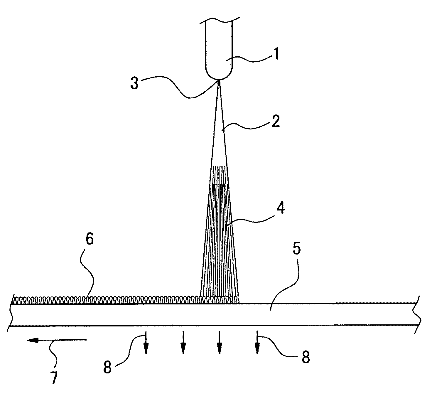
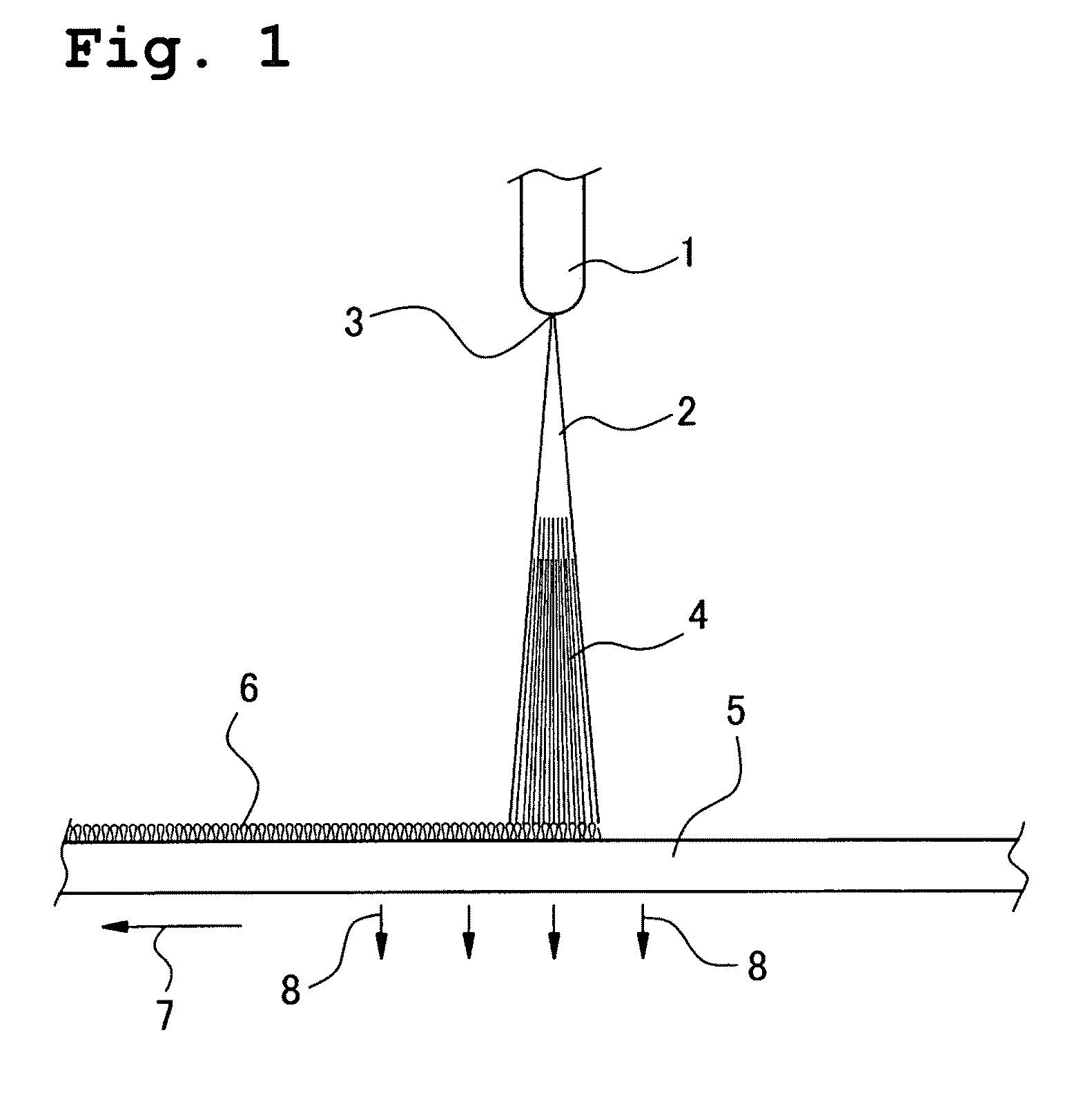
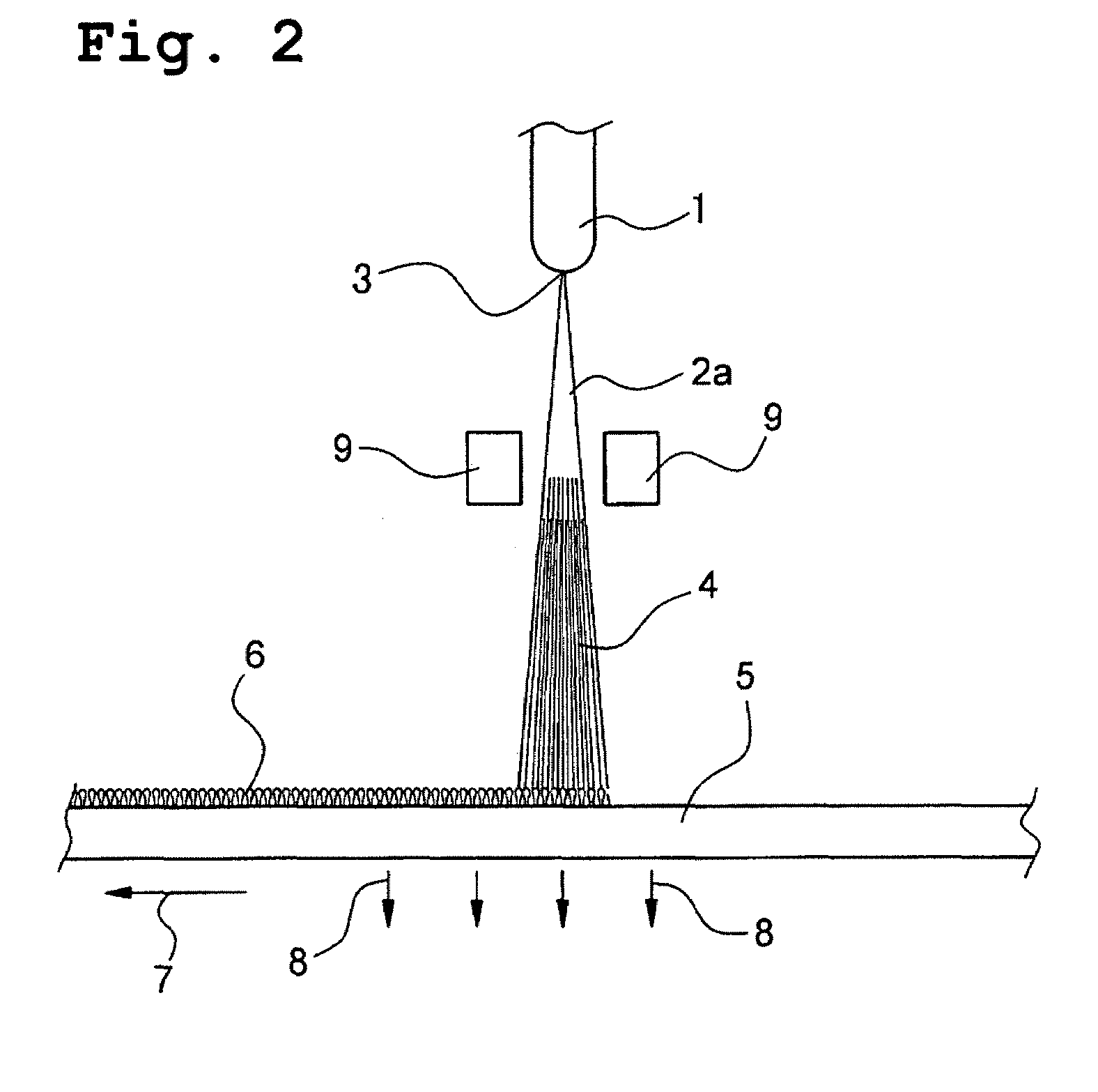
If the quantity of CFRP or the like is reduced in order to meet these demands for weight reduction, then the strength of the resulting product tends to be unsatisfactory.
In this manner, these reinforcing materials are unable to satisfy all the required properties.
Composite materials of carbon fiber and a light metal such as aluminum have been investigated as potential improvements to the situation described above, but the wetting properties of carbon fiber and a light metal are poor, and the light metal and carbon may undergo reaction at high temperatures, causing a deterioration in the strength.
However, a high temperature treatment of at least 1,600° C. is required to produce these types of fibers, and moreover, because these fibers contain phenyl groups, the Si / C elemental ratio is low, and the carbon loss ratio during heat treatment is high, meaning they face problems in terms of conserving resources, and from an economic perspective.
In the methods that use these raw materials, large quantities of hydrogen are generated during the production process, meaning safety can be problematic (patent references 1 and 2).
Exhaust gases discharged from vehicles and industrial machinery and the like cause atmospheric pollution, and are attracting considerable attention.
Particularly in the case of diesel engine vehicles, the removal of NOx and suspended particulate matter comprised mainly of carbon is a significant issue.
A typical exhaust gas purification device for a diesel engine is a structure in which a casing is provided partway along the exhaust pipe connected to the engine exhaust manifold, and a filter having very fine apertures formed therein is then disposed within this casing, but the material for this filter suffers from cracking caused by temperature fluctuations and dissolution loss (patent reference 4).
However, because these materials are short fibers, the material strength tends to be low, and the methods are also extremely expensive due to raw material synthesis problems that require the synthesis of a polysilane from dimethyldichlorosilane, followed by the synthesis of a polycarbosilane or polytitanocarbosilane.

Method used


Image

  • Amorphous inorganic ceramic material and method of producing same
  • Amorphous inorganic ceramic material and method of producing same
  • Amorphous inorganic ceramic material and method of producing same

Examples


example 1

[0197]A meltable silicone resin comprising only MeSiO3 / 2 units as the siloxane units, and containing 5% by mass of hydroxyl groups (molecular weight: 1,000, average compositional formula: Me(OH)0.2SiO1.3, elemental ratio: SiCH3.2O1.5, softening point: 65° C.) (hereinafter, referred to as “meltable silicone resin α”) was subjected to melt spinning under an argon gas atmosphere at a temperature within a range from 130 to 140° C., using a monofilament spinning apparatus with an orifice diameter of 0.05 cm. The speed with which the fiber was wound onto the reel was 250 m / minute. In this manner, a silicone resin fiber with a diameter of approximately 20 μm was obtained. FIG. 3 shows a scanning electron microscope image (scale: 5 μm / division) of the silicone resin fiber obtained.

[0198]The thus obtained silicone resin fiber was immersed in a hydrochloric acid solution with a concentration of 20% by mass, and was left to stand for two days at room temperature. The fibers were then washed wi...

example 2

[0206]With the exception of replacing the meltable silicone resin a used in the example 1 with a meltable silicone resin containing approximately 60 mol % of MeSiO3 / 2 units and approximately 40 mol % of i-PrSiO3 / 2 units as the siloxane units, and containing 5% by mass of hydroxyl groups (molecular weight: 1,000, average compositional formula: (Me)0.6(i-Pr)0.4(OH)0.2SiO1.3, elemental ratio: SiC1.8H4.8O1.5, softening point: 75° C.) (hereinafter, referred to as “meltable silicone resin β”), a black fiber was obtained in the same manner as the example 1. The heating loss ratio was 17.8%, and the black fiber exhibited an elemental ratio of SiC1.2O1.7 and a hydrogen mass fraction of 0.1% by mass or less.

[0207]Determination of the aspect ratio for the fiber (average diameter of fiber / average length of fiber) revealed a result of at least 2,000.

example 3

[0208]With the exceptions of replacing the meltable silicone resin used in the example 1 with a meltable silicone resin containing approximately 60 mol % of PhSiO3 / 2 units, approximately 20 mol % of Ph2SiO units, and approximately 20 mol % of MeSiO3 / 2 units as the siloxane units, and containing 5% by mass of hydroxyl groups (molecular weight: 1,000, average compositional formula: Ph(Me)0.2(OH)0.3SiO1.1, elemental ratio:

[0209]SiC6.2H5.6O1.4, softening point: 92° C.) (hereinafter, referred to as “meltable silicone resin γ”), and replacing the 20% by mass hydrochloric acid treatment with a 98% by mass sulfuric acid treatment, a black fiber was obtained in the same manner as the example 1. The heating loss ratio was 51.2%, and the black fiber exhibited an elemental ratio of SiC1.4O1.5 and a hydrogen mass fraction of 0.1% by mass or less.

[0210]Determination of the aspect ratio for the fiber (average diameter of fiber / average length of fiber) revealed a result of at least 2,000.


PUM

PropertyMeasurementUnit
mass fractionaaaaaaaaaa
diameteraaaaaaaaaa
temperatureaaaaaaaaaa

Abstract

An amorphous inorganic ceramic material including silicon, carbon and oxygen is provided. In the ceramic material, the average elemental ratio between silicon, carbon and oxygen is represented by a compositional formula:SiCaOb wherein, a is a number that satisfies: 0.5≦a≦3.0, and b is a number that satisfies 0.5≦b≦4.0), the material has a siloxane skeleton formed of Si—O—Si bonds, and the hydrogen mass fraction is within a range from 0 to 1% by mass. The material exhibits excellent heat resistance, wettability with other materials, strength and elastic modulus, and is useful as a reinforcing material for composite materials, or as an exhaust gas filter material or the like.

Description

BACKGROUND OF THE INVENTION[0001]1. Field of the Invention[0002]The present invention relates to a novel amorphous inorganic ceramic material that exhibits excellent heat resistance and the like, and a method of producing such a material, as well as an inorganic fiber and an inorganic nonwoven fabric comprising the ceramic material, and methods of producing the fiber and fabric. Moreover, the present invention also relates to a composite material that comprises the inorganic fiber or inorganic nonwoven fabric as a reinforcing material.[0003]2. Description of the Prior Art[0004]Conventionally, glass fiber and carbon fiber are the most widely known reinforcing materials for composite materials. In particular, carbon fiber reinforced plastic (CFRP) exhibits superior levels of strength and elastic modulus to steel or glass fiber reinforced plastic (GFRP), and also offers superior mechanical properties.[0005]However, in recent years, as a result of the demands to reduce the consumption o...

Claims


Application Information

Patent Timeline
Patent Type & Authority Patents(United States)
IPC IPC(8): B32B9/00D02G3/00D04H1/00D04H13/00D04H1/42D04H3/00
CPCC04B14/46C04B35/5603C04B35/571C04B35/62281C04B35/6269C22C47/06C22C49/14D04H3/00C04B30/02D04H1/4209C04B14/4606C04B20/006Y10T442/609C04B2111/00793C04B2235/5252C04B2235/5264C04B2235/5296C04B2235/6562C04B2235/6565C04B2235/6567C04B2235/72C04B2235/96C04B2235/9661Y10T442/60Y10T428/2913Y10T428/2918
Inventor AOKI, YOSHITAKA
Owner SHIN ETSU CHEM IND CO LTD
Why Eureka
Try Eureka