Using the aggregated engine emissions reduction approach requires greater
system costs due to increases in catalyst size or
precious metal loading or necessitates adding additional hardware, such as external systems for
exhaust gas recirculation or
secondary air injection, for realizing further reductions in automobile tailpipe pollutants.
This aggregate technique becomes increasingly expensive, as regulated automobile air
pollutant levels are approaching a zero emissions level, while mandated vehicle emission
system warranty lifetime periods are being greatly increased.
Early catalyst heating further increases the dependency on the catalytic converter since most
air pollution is created during the first 60 seconds following cold engine starts.
High
pollution levels, after engine cold starts, result because most catalyst surfaces must reach temperatures above 100° C. before becoming activated and allowing conversion of toxic exhaust gases into non-toxic forms.
Therefore reducing
time delays before a catalyst's surfaces reach temperatures allowing exothermic
chemical activity further increases the dependency on proper catalytic converter operation for total emission reductions.
However, this also increases dependency on the catalytic converter as the
primary source of
pollutant reductions when total amount of
air pollutants eliminated by the catalyst increases.
However, all the earlier teachings of catalyst heating techniques solely dependent on an
oxygen sensor to provide air-fuel ratio
cycling are therefore unable to operate during open loop fuel control while the cold engine runs rich for stabilizing operation and preventing stalls.
In addition, the magnitudes of catalyst heating possible are typically limited in these prior teachings since they are dependent upon
closed loop fuel control operation where fuel
cycling perturbations beyond 10% may lead to engine control stability concerns.
These stability issues result because a typical switching type zirconia
oxygen sensor can only detect gas characteristics within a few tenths of one air-fuel ratio around the stoichiometric
control point.
Outside this narrow stoichiometric range, a switching type
oxygen sensor can only resolve rich or lean characteristics.
Operation outside this
narrow range leads to control feedback
gain instability because the switching
oxygen sensor can no longer differentiate actual air-fuel ratio errors using the methods taught previously.
However, all the related rapid heating techniques disclosed in prior patents, such as U.S. Pat. Nos. 5,974,790, 5,974,785, 5,661,971, 5,600,948, 5,462,039, 5,357,928, fail to teach methods of early catalyst heating during the time period preceding engine closed loop fuel control activation.
Further, heating methods dependent on closed loop fuel control become increasingly ineffective as lower
thermal mass catalysts are moved closer to the engine
exhaust manifold.
These low
thermal mass catalysts become chemically active within the first 30 seconds of engine cold starting while closed loop fuel control may still be disabled.
Each of these teachings also fail to disclose how control of each individual cylinders' exhaust gases is accomplished since they depend upon aggregate control of air-fuel ratios from a common
oxygen sensor, and thus only during closed loop fuel control engine operation.
While such added hardware provides additional benefits for the methods disclosed herein, such as extending lean limits of operation, they also require use of a more costly in-cylinder
fuel injection systems.
This method is disadvantaged by potentially long indexing periods before estimated individual cylinder fuel corrections are properly indexed with the correct cylinder and also sensitivity to unexpected A / F variations that can occur during normal engine operation.
Such methods provide limited improvements in catalyst exothermic heating because of waiting too long after cold starting and are primarily dependent upon enabling closed
loop control thus limiting increases in rates of heating.
In addition, dependence of these methods on closed
loop control activation using switching type
oxygen sensor feedback results in limited magnitudes of fuel changes due to both stability concerns and of causing increased pollutants if the catalyst hasn't reached sufficient temperatures.
Most catalyst heating is therefore provided by hotter engine exhaust gases caused by ignition retard, and results in increased fuel consumption.
Such methods fail to detect
initiation of catalyst exothermic heating and therefore can only be used when catalyst temperatures are above 400° C. to prevent the potential of higher
air pollutants.
Therefore these methods must wait too long after a
cold start since they are disabled until reaching an estimated light-off catalyst temperature that can change significantly over operational lifetime.
Otherwise, these catalyst heating methods may cause significantly increased
air pollutants in the event that catalyst hasn't reached temperatures sustaining chemical exothermic heating.
These methods use either too limited or more aggressive engine control techniques, such as disabling fuel to some cylinders, which can also cause significant engine roughness.
U.S. Pat. No. 6,202,406 discloses a method of early heating until reaching an estimated catalyst light-off temperature by using a rich A / F, but with no method of providing oxygen to the catalyst for rapid heating, after a cold engine start.
Use of an estimated catalyst light-off temperature, as taught in U.S. Pat. No. 6,202,406, can result in significant delays before methods of exothermic catalyst heating are enabled due to the widely varying temperature range for
initiation of a catalyst's exothermic heating over operational lifetime.
This method also waits too long for effective rapid early catalyst heating under some conditions by using only a static temperature threshold for enabling heating to approximate a widely varying range of light-off catalyst temperatures over a vehicle's lifetime.
And U.S. Pat. No. 6,202,406 determining of catalyst light-off temperature based upon modeling data requiring A / F input dependency creates the potential of large diagnostic and fuel control errors when model data is inaccurate due to unanticipated operational conditions.
These prior teachings fail to disclose methods of diagnosing catalytic converter performance and heating methods while the engine is operated under non-stoichiometric
cold start conditions using a catalyst temperature sensor.
Use of oxygen sensor fluctuations or an estimated catalyst light-off temperature, as taught in all these US patents, can result in significant delays.
Use of an estimated catalyst light-off temperature from modeling algorithms, before enabling methods of exothermic catalyst heating, also delays early heating due to the widely varying temperature range for
initiation of a catalyst's exothermic heating over operational lifetime.
And there are no accurate temperature modeling algorithms that are able to predict the changing temperatures when exothermic heating first occurs as a catalyst deteriorates over time.
Therefore these prior methods result in higher total air pollutants since they cannot account for the wide range of actual, non-static factors influencing this catalyst
activation temperature, such as aging and when condensation occurs on close coupled catalyst active surfaces during some normal environmental operational conditions and
delay activation.
Engine control methods based upon use of static catalyst temperature thresholds don't account for constantly changing operational conditions such as the delayed initiation of catalyst exothermic heating, such as catalytic
converters deteriorate over their useful lifetimes. These prior teachings typically use modeled data or static enabling thresholds in the methods disclosed, such as use of
coolant or a fixed catalyst temperature that can change significantly over a vehicle's operational lifetime and
delay more rapid catalyst heating or diagnosis.
It remains impractical to model catalyst temperatures during many actual operational conditions, such as delayed heating due to condensation on
metal foil surfaces of the catalyst, that many prior methods depend upon for implementing catalyst diagnosis and heating.
However, such conditions can have significant
impact on actual total
air pollution when non-adaptive methods control algorithms are unable to properly adapt for such factors as catalyst condensation during normal engine operation.
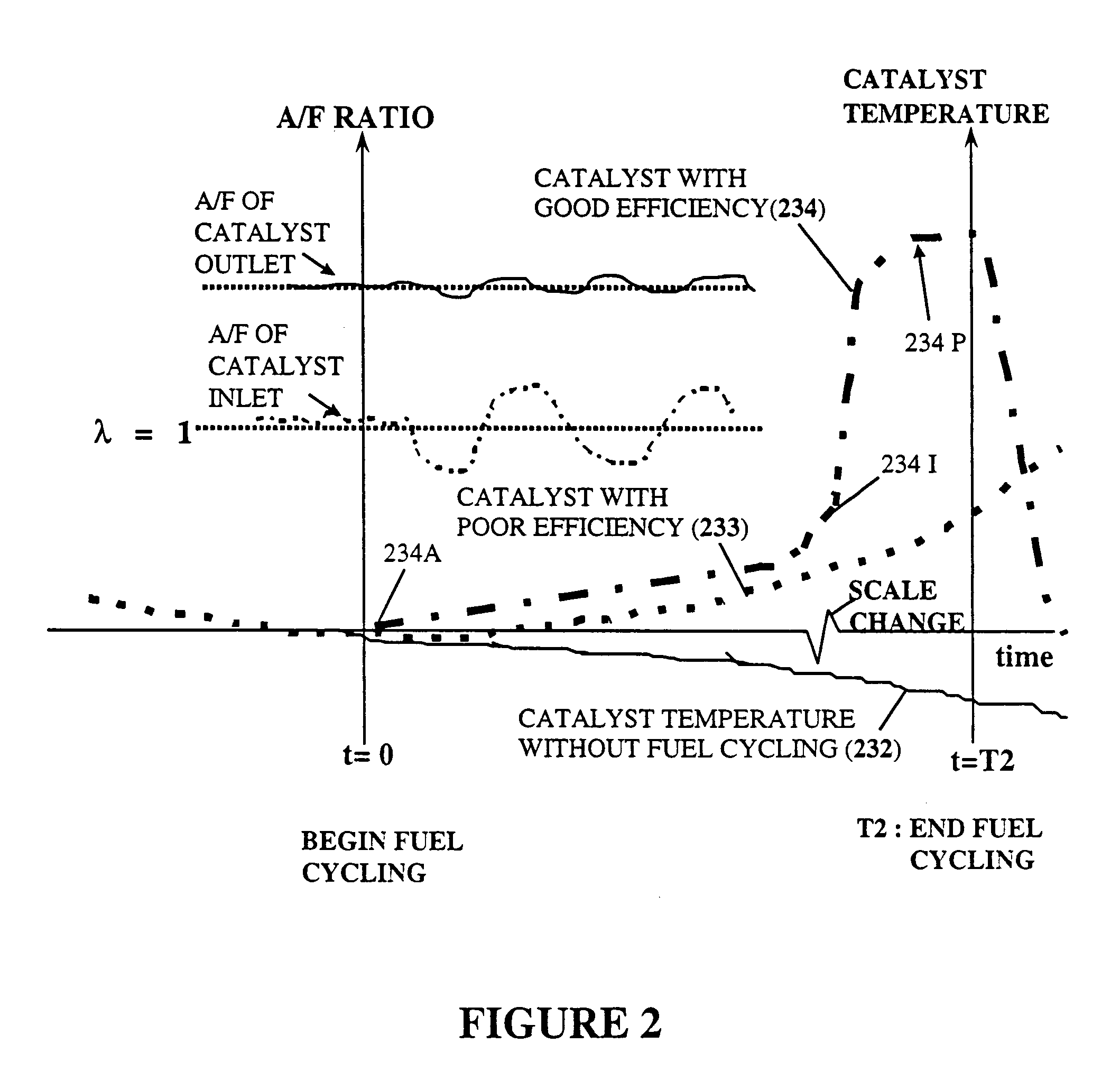
The conversion of these toxic gases into CO2, N2 and H2O results in an exothermic
chemical reaction at the catalyst surface and causes an increase in the temperature of the gases leaving the outlet side of the catalyst element.
The accuracy of oxygen sensor based
diagnostic methods have become less satisfactory as allowed levels of total pollutants from an automobile exhaust into the
atmosphere have been subsequently decreased by new regulations to levels almost approaching zero.
This pulse of unburned fuel and air mixture subsequently enters the catalyst and causes a sudden, small temperature rise in some portion of the catalytic converter's catalyst elements for a short time period.
Since engine operation may not be stable during the required
light load engine enabling conditions, such as engine over run, the consistency of the
chemical energy levels entering the catalyst may also be more variable than desired and degrade catalyst diagnostics accuracy.
However, the critical factor of when to enable the disclosed exothermic heating method, since a catalyst's characteristics are significantly changing in real time during warm-up as well as over the catalyst's operational lifetime, is not disclosed in U.S. Pat. No. 5,715,676.
An alternate solution proposed to resolve this critical enabling time issue in prior methods is by the use of a second catalyst temperature sensor to measure gas temperatures at the catalyst's inlet but adds more cost.
The method disclosed in U.S. Pat. No. 5,896,743 using only a single predefined fixed catalyst temperature threshold, for determining when a catalyst becomes active and begins generating exothermic heating, introduces a
significant error in such diagnosis technique since the catalyst's
activation temperature changes significantly over an automobile's useful lifetime.
Many factors, such as contaminants of the catalyst's surfaces or condensation thereon and actual catalyst light-off temperatures, that vary over the automobile's lifetime, limit such catalyst diagnostic method's accuracy when using such fixed temperature thresholds and multiple unrelated testing methods.
Correspondingly it's common to describe a lean condition with λ>1 when there is less fuel than needed to meet chemical stoichiometric requirements and resulting in
excess oxygen in the exhaust gases.
Availability of cost
effective temperature sensors with either, or both, long term accuracy stability and quick response to changes in the measured gas temperatures remains as one of the main challenges associated with prior methods of catalyst efficiency detection employing
temperature monitoring.
Typically there are tradeoffs between a temperature sensor's
response time characteristics with its durability and cost.
While there are a number of techniques that illustrate how to estimate catalyst temperatures, without need of a temperature sensor, these techniques do not provide accurate catalyst temperatures during unanticipated or abnormal engine operating conditions.
Most of the catalyst temperature
estimation techniques are insufficient for providing the level of
accuracy and precision required for functions such as active catalyst heating and diagnosis by such methods controlling changes in exhaust gases
chemical energy levels.
These fail to teach the important method of detecting initiation of catalyst
chemical activity, where exothermic heating can first occur at a point in time, and thus when fuel control modifications first become effective to aid catalyst exothermic heating.
These also fail to teach methods of actual detection of exothermic heating activation, when a catalyst first becomes chemically active, and are less effective than methods using systems designed with low thermal
mass catalyst systems that can operate under non-stoichiometric
cold start conditions as disclosed in this invention.
They don't disclose methods, such as designing catalyst and temperature sensor systems using low thermal
mass catalyst designs that are capable of detecting actual catalyst chemical heating activation.
Such teachings also fail to allow earlier, more rapid heating by using methods detecting actual initiation of catalyst exothermic activation that employ an expanded range of engine air-fuel ratio control reaching the detectable limits of engine misfire while minimizing perceptible engine roughness yet not requiring cylinder fuel disabling.
These teachings also fail to disclose methods of integrating heating with detection or diagnosing of actual catalyst conversion effectiveness and are therefore unable to heat the catalytic converter to
maximum efficiency in the shortest times possible by modifying fuel control methods based upon its continuing change in catalytic converter characteristics.
In such a situation it may require an indication of catalytic converter malfunction rather than enabling fuel control changes for heating that could increase total air pollutants due to a malfunctioning catalyst.

