
Method for surface treatment of an internal combustion piston and an internal combustion piston

a technology of internal combustion pistons and surface treatment methods, which is applied in the direction of solid-state diffusion coating, machines/engines, manufacturing tools, etc., can solve the problems of internal combustion piston strength decline, weight saving by reducing thickness, and inability to complete combustion, etc., to achieve the effect of improving mechanical strength

Active Publication Date: 2010-08-03
ART METAL MFG +1
View PDF9 Cites 7 Cited by
  • Summary
  • Abstract
  • Description
  • Claims
  • Application Information

AI Technical Summary

Benefits of technology

The present invention provides a method for surface treatment of an internal combustion piston that improves its mechanical strength without causing adverse effects on production efficiency. The method involves injecting injection powders containing a reinforcing element and a photocatalytic element onto the surface of the piston. The reinforcing element improves the strength of the alloy by being diffused and penetrated in the alloy. The photocatalytic element exhibits a photocatalytic function, improving the combustion efficiency and reducing harmful substances in the exhaust gas. The method can also repair surface flaws and fine-grain the metal microstructure near the surface of the piston. The modified layer formed on the piston surface contains the alloy element and the reinforcing element. The method can be performed at a reasonable cost and without affecting production efficiency.

Problems solved by technology

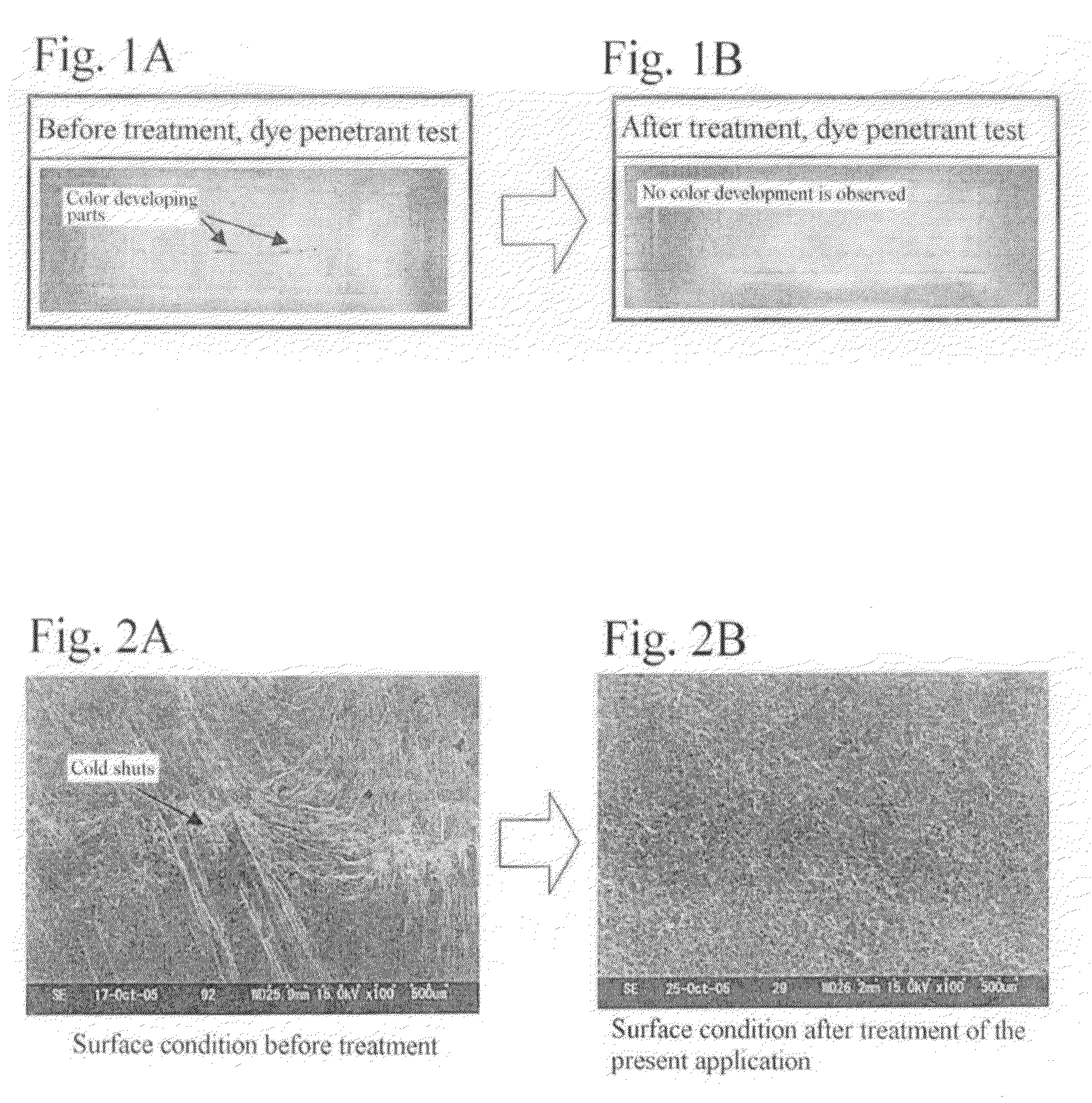
One possible reason for the degradation in strength of the internal combustion piston is, for example, minute surface flaws, such as cold shuts, generated on a casting surface of the internal combustion piston during a casting step.
As a result, weight saving by reducing the thickness becomes difficult.
However, in a direct injection type internal combustion engine, at an ignition stage of the engine, since the temperature of a top surface of the piston is not sufficiently heated, injected fuel is not completely vaporized, and complete combustion cannot be performed.
As a result, there has been a problem in that harmful substances are contained in an exhaust gas.
In addition, in the direct injection type engine as described above, since an injector is provided inside a cylinder, for example, soot is liable to adhere to a nozzle, and the amount of deposited carbon is relatively large as compared to that of a port-type engine.
The deposits caused by adhesion of soot and the like may prevent precise fuel injection in some cases.
Furthermore, the addition of bio fuel, which is being increasingly adopted nowadays, may also produce deposits, and there is some concern that the output and fuel consumption will be degraded thereby.
Among the problems described above, attempts have been made to solve problems such as combustion degradation by the change in volume of a combustion chamber caused by adhesion of deposits; combustion degradation caused by mixed gas combustion occurring before ignition using an ignition plug; and an increase in the amount of harmful exhaust components generated and discharged from deposits, for example, by removing soot generated by combustion of fuel in the combustion chamber, and deposits formed by adhesion of lubricants coming into the combustion chamber and unburned fuel components to the inner surface of the combustion chamber.
Problems with Previous Methods for Improving Mechanical Strength
Problems with Improving Mechanical Strength During a Casting and / or Forging Step
As a result, the manufacturing cost of the internal combustion piston increases.
In addition, according to the current technical level, although the generation of surface flaws, such as cold shuts, can be reduced by improving the process, equipment, and the like as described above, it cannot be completely prevented.
In addition, according to the method for improving the strength of an internal combustion piston by changing the composition of the alloy components comprising the internal combustion piston, although the strength can be effectively increased, it is difficult to form uniformly fine-grained alloy components during casting.
As a result, in some cases there may be problems such as the mechanical strength not being sufficiently improved, the quality being variable, and so on.
In addition, the improvement in material strength causes degradation in casting and forging properties and workability; in particular, as the strength is increased, cutting workability is seriously degraded.
Accordingly, since the improvement in strength as described above causes degradation in the production efficiency of internal combustion pistons and an increase in manufacturing costs, it is difficult to simply increase the strength.
Hence, the fine particles are liable to peel off or fall from the surface portion, and once they peel off or fall, improvement in the mechanical strength due to the inherent properties of the fine particles cannot be expected.
As a result, the treatment time and costs increase due to the increased number of steps.
H5-86443, no mechanism for repairing the surface flaws as described above is provided, and in addition, the embedment of the fine metal particles in the aluminum alloy member as described above actually exacerbates notch embrittlement.
In addition, according to the technique in the related art, improvement in strength in a high-temperature region in which a piston is used has not been disclosed, and although a conventional surface treatment, such as shot peening or heat treatment, can improve the strength in a room-temperature region by the effects of residual stress, surface hardening, and the like, in a high-temperature region, which is the particular temperature region where the piston is used, the stress is released, so that the effects disappear.
However, when the temperature inside the combustion chamber is not sufficiently increased at a starting stage, the conditions necessary for sufficiently obtaining this catalytic function cannot be satisfied, and as a result, the catalytic function does not work.
Hence, according to the technique disclosed in Japanese Patent No. 3541665, since the effect of decomposing organic materials and the effect of modifying the fuel cannot both be obtained immediately after starting the internal combustion engine, the fuel efficiency immediately after starting cannot be improved, and as a result of the incomplete combustion and the like, harmful substances are discharged together with the exhaust gas.

Method used


Image

  • Method for surface treatment of an internal combustion piston and an internal combustion piston
  • Method for surface treatment of an internal combustion piston and an internal combustion piston
  • Method for surface treatment of an internal combustion piston and an internal combustion piston

Examples


examples

[0153]Next, experimental examples of surface treatment by the method according to the present invention will be described.

Confirmation Test for Repair of Surface Flaws and Formation of Modified Layer

Purpose of Experiment

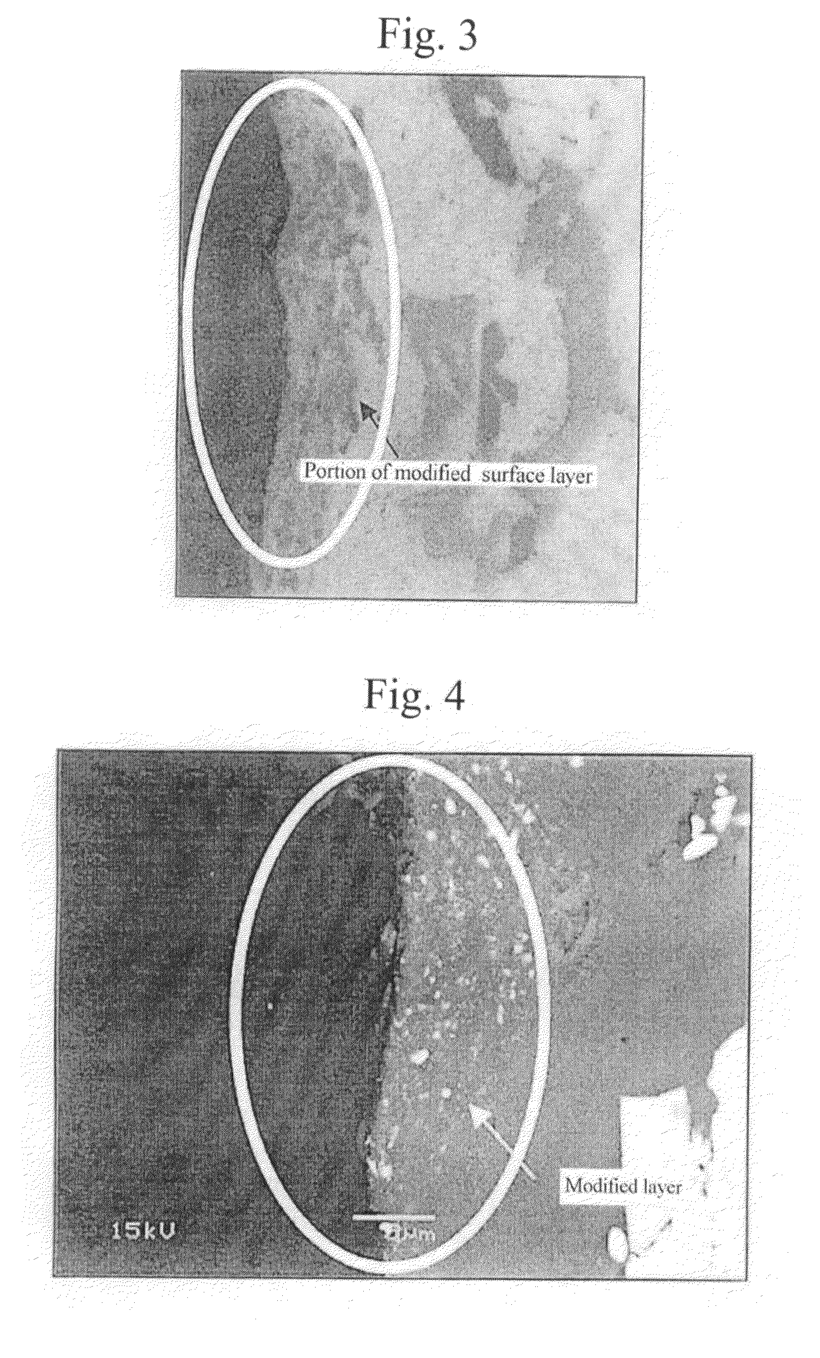
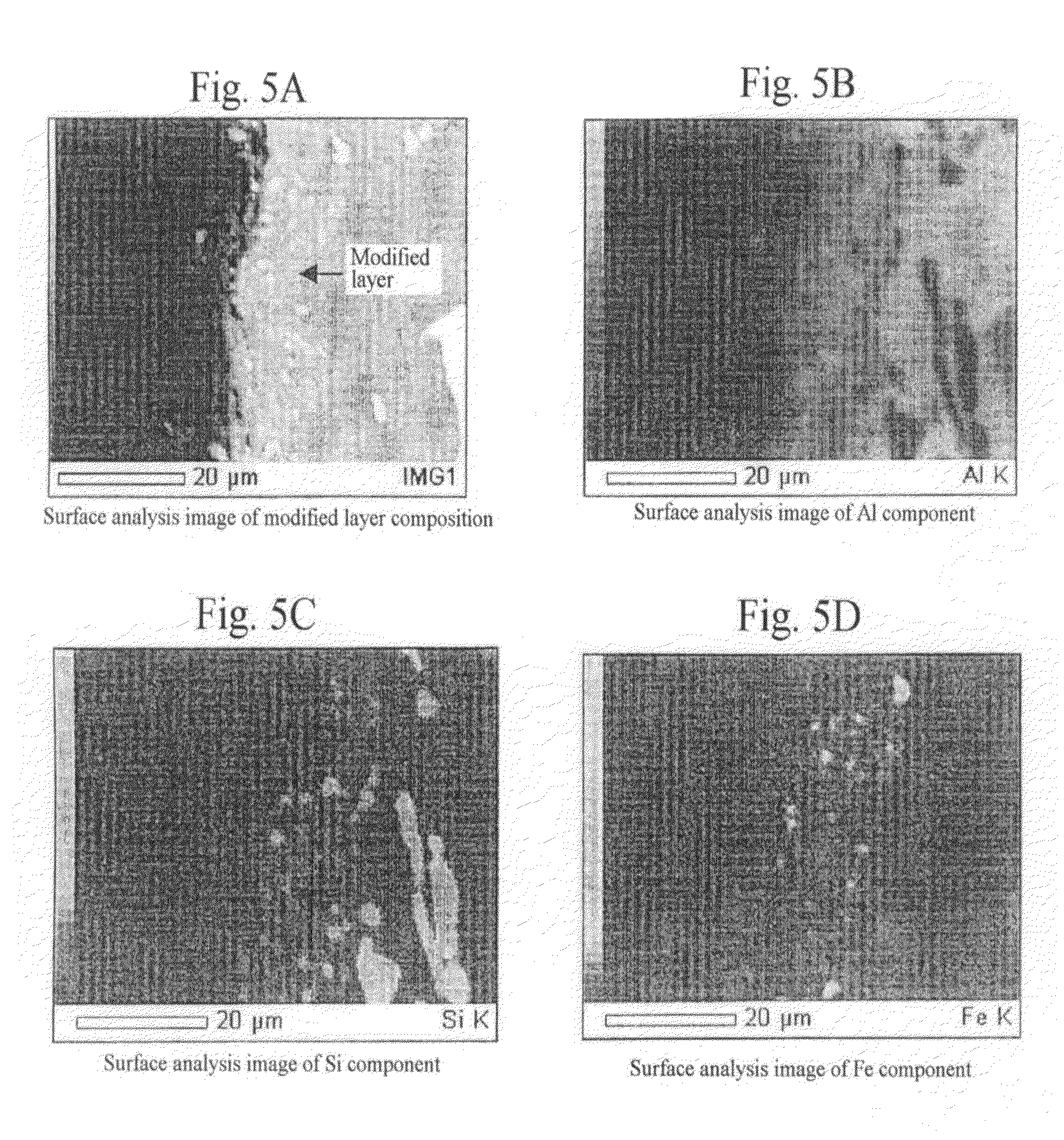
[0154]By performing surface treatment of the method according to the present invention, it is confirmed whether surface flaws of an internal combustion piston can be repaired, and whether a modified surface layer can be formed from the surface thereof to a predetermined depth.

Experimental Method

[0155]By using materials shown in Table 4 below, injection powders were injected on an Al—Si composition (internal combustion piston) shown in Table 2 under the treatment conditions shown in Table 3.

[0156]

TABLE 2Object to be treatedObject to be treatedPiston for a gasoline engineMaterialTable 4 (Al-12% Si, and others)Treatment portionSee FIG. 10Area of treatment portionApproximately 80 mm in diameter, Entireinner surface

[0157]

TABLE 3Treatment conditionsInjection powdersMateria...

example 9

[0221]

Experimental engineInline four-cylinder diesel engine (Turbo with intercooler)Use fuelStandard light fuelLubricant10W-30 CF-4

Experimental Results

[0222]Carbon Adhesion State

[0223]The results of carbon adhesion to the pistons are shown in Table 10.

[0224]

TABLE 10Carbon Deposition on the Piston Top SurfaceCylinder No.1 (injected3 (injectedwith Sn)2 (Untreated)with Ti)4 (Untreated)CarbonNoYesNoYESDeposition

[0225]Exhaust-Gas Temperature

[0226]According to the measurement results of temperatures (average value for 60 seconds) of exhaust gas discharged from the cylinders, although the exhaust-gas temperatures of the second and fourth cylinders fitted with the untreated pistons were approximately 670° C., it was confirmed that the exhaust-gas temperature of the first cylinder fitted with the piston treated by injecting injection powders containing powdered tin and that of the third cylinder fitted with the piston treated by injecting injection powders containing powdered titanium were l...


PUM

PropertyMeasurementUnit
diameteraaaaaaaaaa
temperatureaaaaaaaaaa
velocityaaaaaaaaaa

Abstract

A method for surface treatment capable of easily improving a mechanical strength of an internal combustion piston at a reasonable cost is provided. A modified surface layer is formed by injecting injection powders containing a reinforcing element to be collided with an Al—Si alloy-based piston obtained by casting and forging by injecting under predetermined conditions, the reinforcing element being diffused and penetrated in the piston to improve the strength thereof. When a function, such as fuel modification, is imparted to the modified surface layer, an element exhibiting a photocatalytic function by oxidation, such as Ti, Sn, Zn, Zr, or W, is selected as the reinforcing element. By locally heating and cooling performed on the piston surface by the collision with the injection powders, alloy elements are fine-grained by recrystallization, the reinforcing element in the injection powders is diffused and penetrated in the piston surface by activated adsorption, and a modified layer having a uniformly fine-grained microstructure containing the alloy elements and the reinforcing element is formed. As a result, besides improvement in strength of the piston, by the selection of the above element, such as Ti, the photocatalytic function, such as fuel modification, can also be obtained.

Description

BACKGROUND OF THE INVENTION[0001]1. Field of the Invention[0002]The present invention relates to methods for surface treatment of internal combustion pistons and to internal combustion pistons, and more particularly, relates to a method for surface treatment of an internal combustion piston performed by injecting and colliding injection powders on the surface thereof and to an internal combustion piston modified the surface by the above method.[0003]2. Description of the Related Art[0004]An internal combustion piston performs a reciprocating motion repeatedly under explosive pressure and high temperature conditions. Accordingly, the internal combustion piston is required to have a high strength.[0005]On the other hand, in order to reduce fuel consumption, it is necessary to save weight by reducing thickness, and as a result, contradictory requirements, that is, increasing strength and saving weight must be satisfied simultaneously.[0006]In particular, in recent years where environme...

Claims


Application Information

Patent Timeline
Patent Type & Authority Patents(United States)
IPC IPC(8): C23C8/00B23P15/10B41N1/24F02F3/00
CPCF02F3/10Y10T29/49263Y10T29/49261
Inventor FUJIWARA, NOBUYUKIMIYASAKA, YOSHIO
Owner ART METAL MFG
Learn More