
Fine dry silica particles

a technology of dry silica and fine silica, which is applied in the field of fine dry silica particles, can solve the problems of increasing the occurrence of defects, and reducing the amount of fumed silica used, so as to achieve sufficient strength and suppress the rise of viscosity

Active Publication Date: 2010-09-28
TOKUYAMA CORP
View PDF16 Cites 11 Cited by
  • Summary
  • Abstract
  • Description
  • Claims
  • Application Information

AI Technical Summary

Benefits of technology

The resulting fine silica particles effectively disperse in resins, prevent viscosity increases, enhance gap permeability, maintain fluidity in toner additives, and improve the reliability and durability of semiconductor and electrophotography applications.

Problems solved by technology

In recent years, semiconductor chips are generating heat in increased amounts accompanying the trend toward higher degree of integration and higher operation speed of semiconductor chips, causing an increase in the occurrence of defects stemming from the discrepancy of thermal expansion between the semiconductor chip and the molding compound for sealing it or a circuit board (particularly, laminated circuit board) mounting the semiconductor chip thereon.
If added in an increased amount, therefore, it becomes difficult to form the resin (resin composition).
Namely, limitation is imposed on the amount of using the fumed silica.
Further, the fumed silica contains, as an impurity, chlorine that stems from the chlorosilane which is the starting material and brings about a defect of corroding metal wiring and the like.
However, the spherical silica not only much contains coarse particles of several microns or larger stemming from the production method but also exhibits strong aggregating property and much contains aggregated particles which cannot be easily dispersed in the resin.
As a result, the resin compound to which the spherical silica is much added exhibits poor gap permeability, clogs among the wirings, and deteriorates the reliability of equipment to which the resin compound is applied.
However, the filler material having a broad particle size distribution disperses unhomogeneously in the resin composition, developing local dispersion in the coefficient of thermal expansion and forming portions where the coefficient of thermal expansion greatly differs.
However, the fine fumed silica particles used as the toner additive have a branched structure in which the primary particles are melt-adhered, exhibit a less effect for imparting fluidity than the individual spherical particles and, further, have a small primary particle size allowing silica particles to sink below the surfaces of the toner resin particles due to external stress such as stirring, without playing the role of antiblocking for extended periods of time, allowing the fluidity of the toner to gradually decrease, making it difficult to scratch off the residual toner by the cleaning blade and causing inconveniences such as a decreased transfer efficiency at the time of forming the picture and a decreased picture equality due to filming phenomenon.
However, a too large particle size decreases the effect for improving the fluidity.
Therefore, sinking in the toner resin particles is not prevented even if there is used a toner additive having too large particle sizes.
Further, the toner additive containing hard and coarse particles of not smaller than several microns becomes a cause of impairing the durability of the photosensitive material drum due to abrasion.
However, the toner additive having a broad particle size distribution disperses or adheres unhomogeneously arousing a problem in controlling the electric charge and causing a decrease in the picture quality.
Even when metals such as iron and sodium, as well as chlorine are contained as impurities, the amount of electric charge decreases and it becomes difficult to control the electric charge.
However, the particles aggregate firmly in the steps of drying and firing for removing water contained in the silica arousing a problem of formation of coarse particles.
As a result, fine silica particles do not collide together to grow and it becomes difficult to obtain silica particles of a size adapted to the use as a filler.
Even if particles were obtained having desired sizes, there are much contained poorly dispersing particles stemming from the melt-adhesion of primary particles.
However, since the starting material (silicon powder) is a solid powder, it is difficult to feed the starting material at a constant rate maintaining stability though the feeding rate can be increased.
Due to fluctuation in the feed of the starting material, therefore, the concentration of silica source varies in the flame and it becomes difficult to obtain fine silica particles having a sharp particle size distribution without containing coarse particles.
Further, even if the starting material can be fed maintaining stability, the particle size distribution stemming from the starting powder tends to vary or the concentration tends to vary due to the deviation of the starting material in the flame making it difficult to obtain fine silica particles having a sharp particle size distribution without containing coarse particles.
In the case of the spray combustion of (4), the starting material that is used is a liquid (liquid siloxane) and can be easily fed maintaining stability accompanied, however, by the difficulty in adjusting the droplets that are sprayed to possess a predetermined size.
Besides, the liquid droplets may be present in some places but may not be present in other places causing a difference in the concentration of silica source in the flame and making it difficult to obtain fine silica particles having a sharp particle size distribution without containing coarse particles.
Therefore, the methods (1) to (4) are not adapted to obtaining silica particles having the above-mentioned properties (a) to (c).
According to the above diffusion combustion method, the mixed state of the siloxane gas and the combustion-sustaining gas greatly affects the state of combustion of the siloxane or the formation and growth of the fine silica particles making it, however, very difficult to control the mixing of the gases in a diffused state and, therefore, difficult to control the particle size distribution of the obtained fine silica particles.
Further, without separately introducing oxygen in an excess amount into the burner, the siloxane does not burn completely, carbon soot forms, and fine silica particles are not obtained.
However, no method has yet been known to control properties such as particle size distribution of the obtained fine silica particles, and the silica particles having the above properties (a) to (c) have not yet been obtained.
However, no technology is yet available for removing particles of about 3 to 5 μm by dry classification method such as cyclone or pneumatic classification.
These means, however, require the step of drying fine particles causing the particles to be strongly aggregated together at the time of drying and rather forming coarse particles.
After all, there is at present no method of controlling the fine silica particles for their particle size distribution relying upon the classification.

Method used


Image

  • Fine dry silica particles

Examples


examples

[0122]The invention will now be described below concretely by way of Examples and Comparative Examples to which only, however, the invention is in no way limited.

[0123]In the following Examples and Comparative Examples, various properties were measured in compliance with the methods described below.[0124](1) Measurement of Specific Surface Areas:

[0125]Measured according to the nitrogen adsorption BET 1-point method by using an apparatus for measuring specific surface area (SA-1000) manufactured by Shibata Rikagaku Co.[0126](2) Measurement of Optical Absorbance:

[0127]An aqueous suspension of a silica concentration of 1.5% by weight was measured for its absorbance τ for light of a wavelength of 700 nm by using a spectrophotometer (V-530) manufactured by Nihon Bunkosha Co.

[0128]The sample cell to be measured was a synthetic quartz cell (having 5 clear surfaces, 10×10×45H) manufactured by Tokyo Garasu Kikaisha Co.

[0129]The aqueous suspension having a silica concentration of 1.5% by weig...

examples 1 to 5

, Comparative Examples 1 to 3

[0145]Fine silica particles were produced by burning the octamethylcyclotetrasiloxane using the triple-pipe burner as described below.

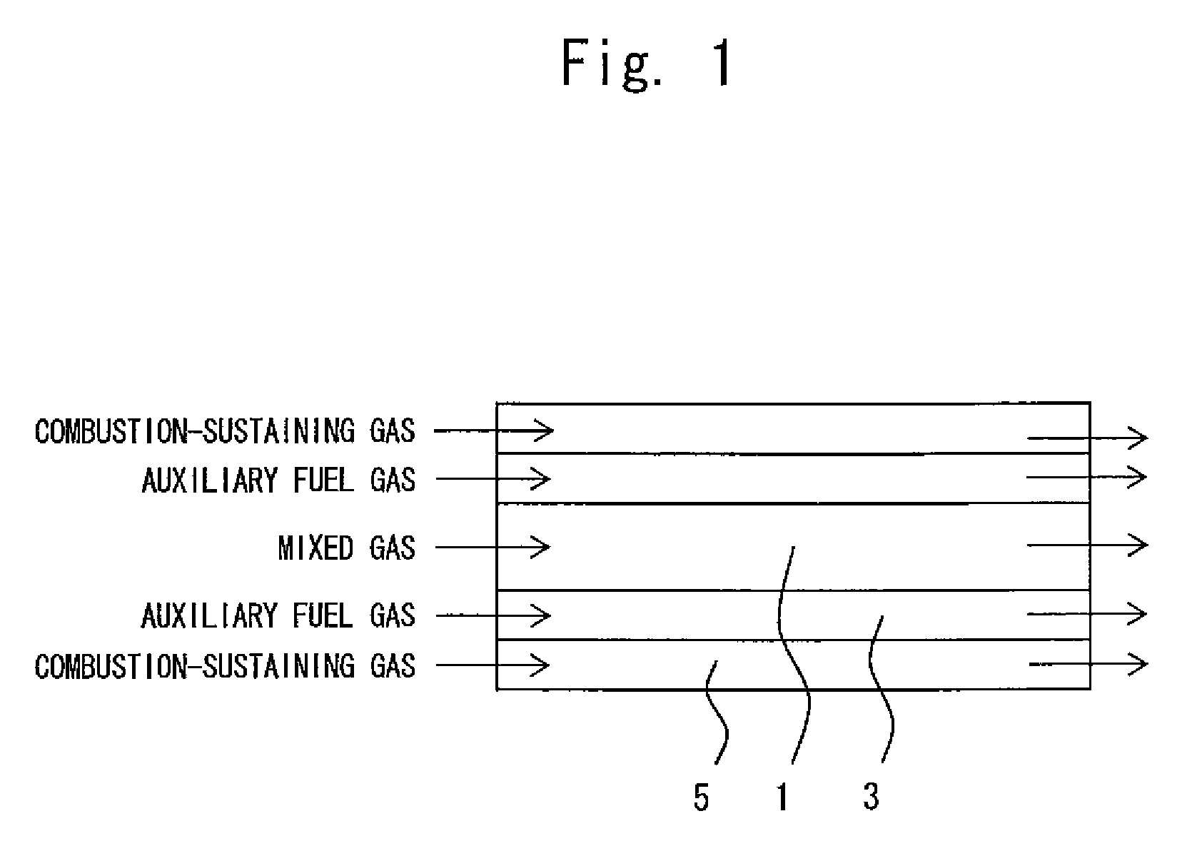
[0146]The heated and gasified octamethylcyclotetrasiloxane, oxygen and nitrogen were mixed together, and were introduced into the center pipe of the burner. Hydrogen was introduced as the auxiliary fuel gas into the first annular pipe neighboring the center pipe, and oxygen was introduced as the combustion-sustaining gas into the second annular pipe neighboring on the outer side thereof. The production conditions were as shown in Table 2 (in Example 5, the fine silica particles were produced under quite the same conditions as those of Example 1 but without introducing the combustion-sustaining gas into the second annular pipe).

[0147]Table 2 also shows specific surface areas S of the fine silica particles, residual amounts on the electroformed sieves of perforation sizes of 5 μm and 3 μm, optical absorbance absorbencies τ o...


PUM

PropertyMeasurementUnit
BET specific surface areaaaaaaaaaaa
perforation sizeaaaaaaaaaa

Abstract

Fine dry silica particles are produced by combustion by using a burner of a multiple-pipe structure, feeding a mixed gas of a gas of a siloxane compound without containing halogen in the molecules thereof and an oxygen gas at a ratio of 0.3 to 1.5 into the center pipe of a burner, and feeding a combustible gas into the first annular pipe on the outer side of the center pipe of the burner. The fine dry silica particles has a BET specific surface area of 20 to 55 m2 / g, and wherein the water suspension containing the fine silica particles at a concentration of 1.5% by weight has an optical absorbance τ for the light of a wavelength of 700 nm satisfying the following formula (1):τ≦240S−1.4−0.07  (1)wherein S is the BET specific surface area (m2 / g) of the fine dry silica particles.The fine dry silica particles do not almost contain coarse particles or aggregated particles, have a sharpe grain size distribution, excellently disperse in the resins, suppress a rise in the viscosity when highly filled, and impart sufficiently large strength to the resin compound.

Description

FIELD OF THE INVENTION[0001]The present invention relates to fine dry silica particles that can be favorably used as a filler for a resin compound which is used as a molding compound for semiconductor devices, as a sealing material for liquid crystals or as an insulating material for laminated circuit boards, or that can be favorably used as a toner additive for electrophotography.BACKGROUND ART[0002]In recent years, semiconductor chips are generating heat in increased amounts accompanying the trend toward higher degree of integration and higher operation speed of semiconductor chips, causing an increase in the occurrence of defects stemming from the discrepancy of thermal expansion between the semiconductor chip and the molding compound for sealing it or a circuit board (particularly, laminated circuit board) mounting the semiconductor chip thereon. This tendency is requiring an increase in the amount of the filler added to the molding compound for semiconductor chips or added to t...

Claims


Application Information

Patent Timeline
Patent Type & Authority Patents(United States)
IPC IPC(8): C01B33/12
CPCC01B33/181G03G9/09725C08K3/36Y10T428/2982C01B33/18
Inventor OHARA, MASAKAZUTAKATA, YUKIHIROAOKI, HIROOUEDA, MASAHIDE
Owner TOKUYAMA CORP
Learn More