
Multi-source plasma focused ion beam system

a plasma focused ion beam and beam technology, applied in the field of ion beam systems, can solve the problems of increasing processing time, limiting the reaction rate by adsorption rate, and disadvantages of using lmis, and achieve the effect of sequential or simultaneous facilitation

Active Publication Date: 2011-12-13
FEI CO
View PDF38 Cites 47 Cited by
  • Summary
  • Abstract
  • Description
  • Claims
  • Application Information

AI Technical Summary

Benefits of technology

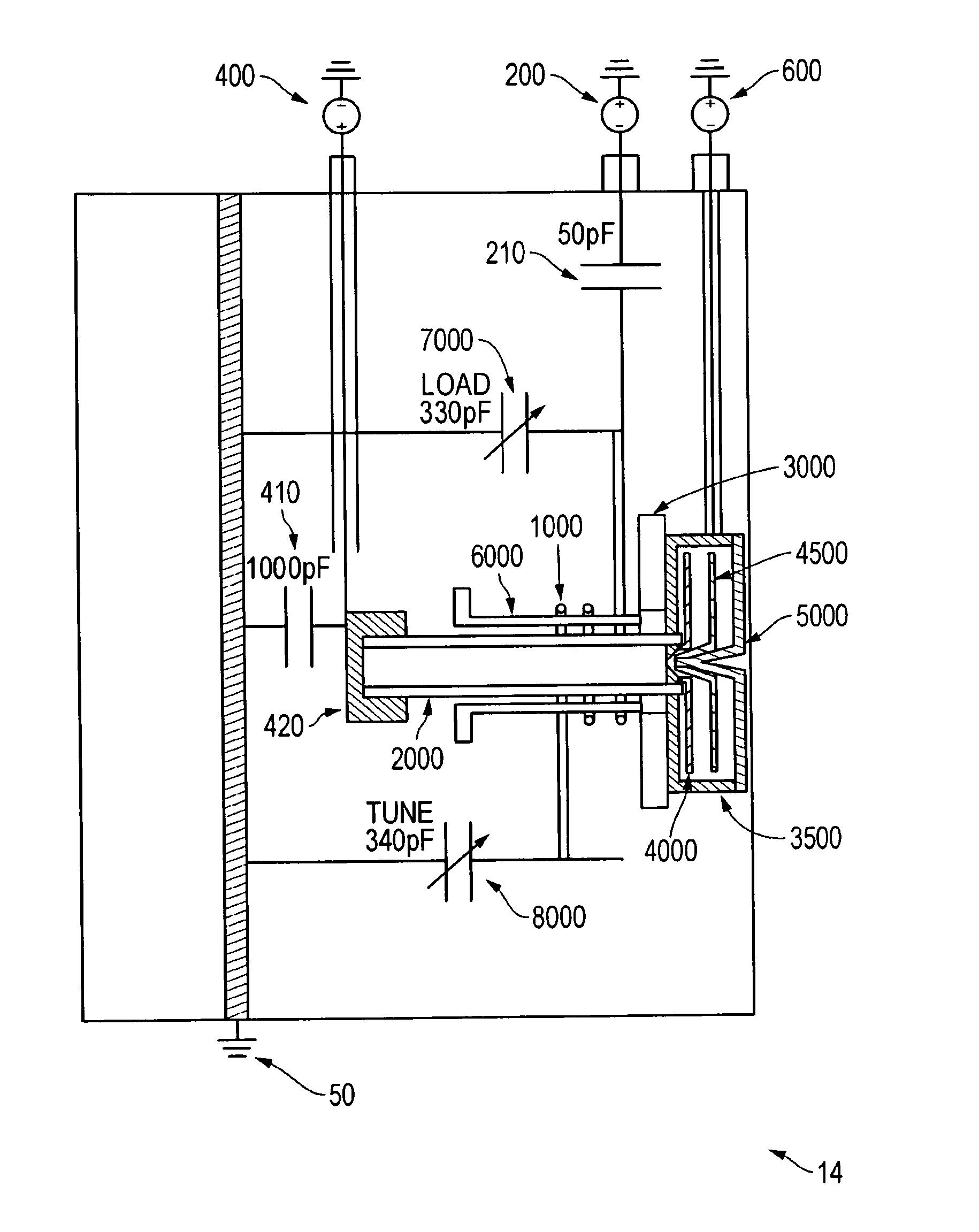
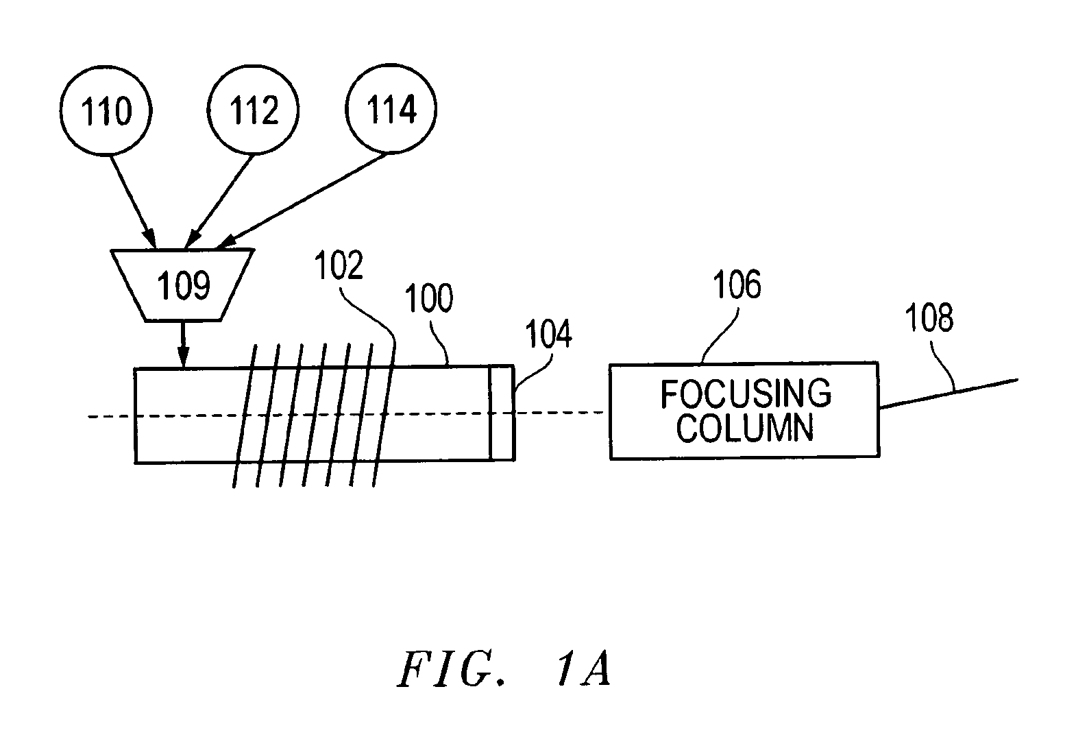
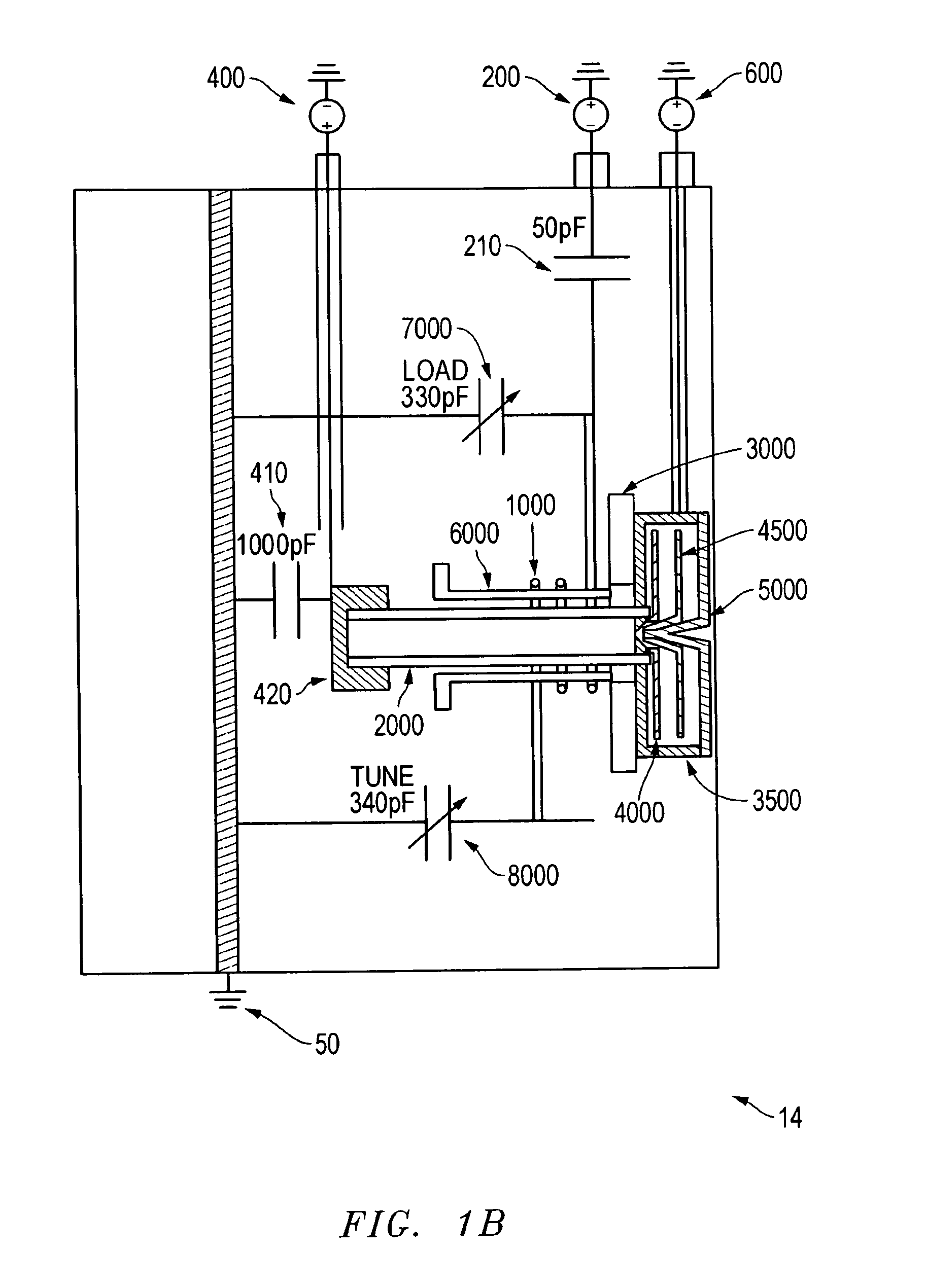
[0012]Embodiments of the invention provide a method and apparatus for performing multiple charged particle beam operations on a work piece and provide for the use of different types of charged particles to operate on a work piece in a single system. The invention facilitates sequentially or simultaneously using different ion species to perform various processes on a work piece. The different processes can be performed with the most appropriate charged particle species for that particular process.
[0013]For example, an inert ion specie can be used to sputter or to activate an etch-enhancing gas or a deposition precursor gas adsorbed onto the substrate. In another example, the charged particle beam itself may include an etch-enhancing gas or a deposition precursor gas, thereby eliminating the necessity of using a beam of one species to provide the activation energy for a compound introduced through a gas injection system. In yet another example, the beam species can comprise a material to be directly deposited.

Problems solved by technology

There are disadvantages to using LMIS'S.
With regard to chemically-assisted etching or deposition, because the gallium itself merely provides energy for the reaction and does not otherwise participate, the reaction rate is limited by adsorption rate of the reacting molecules.
This increases processing time.
Moreover, gallium atoms implant into the work piece and, in many applications, produce undesirable side effects, such as changing the opacity or electrical properties of a work piece.
Gallium can also disrupt the crystal structure in the area of bombardment.
The type of ion emitted from a LMIS cannot be readily changed, which is a disadvantage because different ion species may be preferred for different processes.
To change the ion species, the source must be removed from the vacuum chamber and replaced with a different source, which must then undergo a time consuming preparation procedure.
Such systems, however, typically provide a reactive plasma over the entire surface of a wafer and are not used to locally etch or deposit fine features.
Plasma ion sources have been used to form ion beams, but such beams are not typically used to mill or deposit fine features on a work piece because beams from plasma ion sources were difficult to focus into a fine spot while maintaining a useful beam current.
Moreover, such plasma sources are limited to the specific types of gases and the lifetime of such sources are relatively short with some gases because the plasma would corrode the cathode.

Method used


Image

  • Multi-source plasma focused ion beam system
  • Multi-source plasma focused ion beam system
  • Multi-source plasma focused ion beam system

Examples


Embodiment Construction

[0024]The following is a detailed description of example embodiments of the invention depicted in the accompanying drawings. The example embodiments are in such detail as to clearly communicate the invention. However, the amount of detail offered is not intended to limit the anticipated variations of embodiments; on the contrary, the intention is to cover all modifications, equivalents, and alternatives falling within the spirit and scope of the present invention as defined by the appended claims. The detailed descriptions below are designed to make such embodiments obvious to a person of ordinary skill in the art.

[0025]Embodiments of the invention provide for processing of submicron features using charged particle beams. In a preferred embodiment, a work piece can be sequentially processed with relatively high current using submicron beams of different ion species, without removing the work piece from the vacuum chamber and without having to change the ion source, that is, the plas...


PUM

PropertyMeasurementUnit
energy spreadaaaaaaaaaa
beam energyaaaaaaaaaa
sizeaaaaaaaaaa

Abstract

The present invention provides a plasma ion beam system that includes multiple gas sources and that can be used for performing multiple operations using different ion species to create or alter submicron features of a work piece. The system preferably uses an inductively coupled, magnetically enhanced ion beam source, suitable in conjunction with probe-forming optics sources to produce ion beams of a wide variety of ions without substantial kinetic energy oscillations induced by the source, thereby permitting formation of a high resolution beam.

Description

TECHNICAL FIELD OF THE INVENTION[0001]The present invention relates to the field of ion beam systems.BACKGROUND OF THE INVENTION[0002]A typical focused ion beam (FIB) system using a gallium liquid metal ion source (LMIS) can provide five to seven nanometers of lateral resolution. Such systems are widely used in the characterization and treatment of materials on microscopic to nanoscopic scales. A gallium LMIS typically comprises a pointed needle coated with a layer of gallium. The needle may be maintained at a high temperature while an electric field is applied to extract ions from the source.[0003]FIB systems with gallium LMIS's are used in many applications because of their ability to image, mill, deposit, and analyze with great precision. Milling or micromachining involves the removal of bulk material at or near the surface. Milling can be performed without an etch-assisting gas, in a process called sputtering, or using an etch-assisting gas, in a process referred to as chemicall...

Claims


Application Information

Patent Timeline
Patent Type & Authority Patents(United States)
IPC IPC(8): G21G5/00
CPCC23C14/0031H01J37/3007H01J37/08H01J37/305H01J37/3056H01J37/3178H01J37/32082C23C14/221H01J37/3053H01J37/3211H01J27/16H01J2237/006H01J2237/0817H01J2237/0827H01J2237/31H01J2237/31749
Inventor SMITH, NOELCHANDLER, CLIVE D.UTLAUT, MARKTESCH, PAUL P.TUGGLE, DAVE
Owner FEI CO
Learn More