Reversed-polarity pulse generating circuit for direct current plasma and direct current plasma power supply unit

a pulse generating circuit and plasma technology, applied in the direction of electric variable regulation, process and machine control, instruments, etc., can solve the problems of short circuit between electrodes, plasma discharge occurring in vacuum in the plasma load may temporarily become abnormal electrical discharge, and the breakdown voltage of the switching element for reversed-polarity voltage application can be reduced, surge voltage can be reduced, and noise can be reduced

Inactive Publication Date: 2013-06-25
ORIGIN ELECTRIC CO LTD
View PDF8 Cites 9 Cited by
  • Summary
  • Abstract
  • Description
  • Claims
  • Application Information

AI Technical Summary

Benefits of technology

[0015]An object of the present invention is to reduce the surge voltage occurring when turning off a switching element for reversed-polarity voltage application, and to reduce the voltage applied to the switching element for reversed-polarity voltage application, as compared to conventional circuit configurations.
[0017]By employing such a configuration, before plasma ignition, the voltage at both ends of the capacitor is divided in two by way of the voltage balance resistors connected in parallel with each of the switching elements for reversed-polarity voltage application; therefore, approximately only ½ of the voltage at both ends of the capacitor is applied to each of the switching elements for reversed-polarity voltage application. Moreover, when turning off the switching elements for reversed-polarity voltage application, which were conductive in order to generate a reversed-polarity pulse, a feedback diode is made conductive, and returns the energy stored in the inductance means to the capacitor, and the voltage of the capacitor restricts the voltage at both ends of the switching elements for reversed-polarity voltage application. Therefore, as compared to conventional cases, the present invention can considerably reduce the surge voltage, and can also reduce the voltage applied to both ends of the switching elements for reversed-polarity voltage application when turning off the switching elements. In addition, the noise due to the surge voltage can also be reduced.
[0018]Furthermore, according to the present invention, since a switching element with a low rated voltage can be used, a semiconductor switch such as an FET (field effect transistor) with small ON resistance and superior switching speed can be used as the switching element for reversed-polarity voltage application. Accordingly, the cycle for applying a reversed-polarity voltage pulse to the plasma load can be made a high frequency. As a result, the influence on the plasma load can be reduced as much as possible as compared to conventional cases, and occurrence of abnormal electrical discharge such as arc discharge can be prevented more reliably.
[0022]Furthermore, by employing such a configuration, the breakdown voltage of the switching element for reversed-polarity voltage application can be lowered, the surge voltage can be reduced, the noise can be reduced, and the power loss can also be reduced.
[0023]The direct current plasma power supply unit according to the present invention includes any of the reversed-polarity pulse generating circuits for direct current plasma as described above. By employing such a configuration, similarly to the reversed-polarity pulse generating circuit for direct current plasma as described above, the breakdown voltage of the switching element for reversed-polarity voltage application can be lowered, the surge voltage can be reduced, the noise can be reduced, and the power loss can also be reduced.
[0024]According to the present invention, when the switching element for reversed-polarity voltage application is turned off, the voltage of the capacitor restricts (clamps) the voltage at both ends of the switching element for reversed-polarity voltage application; therefore, the surge voltage can be reduced, and the power loss due to the surge voltage can be reduced. In addition, before plasma ignition, i.e. before generating plasma discharge, the voltage of the capacitor is shared by the voltage balance resistors connected in parallel with each of the switching elements for reversed-polarity voltage application; therefore, the voltage applied to the switching elements for reversed-polarity voltage application can be reduced as compared to conventional circuit configurations.

Problems solved by technology

Conventionally, in a direct current plasma device that utilizes a plasma discharge generated in vacuum, such as a sputtering device, a PVD (Physical Vapor Deposition) device, a CVD (Chemical Vapor Deposition) device, and an etching device, impedance between electrodes in the plasma load may be reduced, or foreign matter such as conductive dust may result in a short circuit between the electrodes.
In such a case, the plasma discharge occurring in vacuum in the plasma load may temporarily become an abnormal electrical discharge such as an arc discharge.
In particular, if such an abnormal electrical discharge occurs in a sputtering device, the target may melt.
In a sputtering device, for example, if the target melts while sputtering a substrate material such as a liquid crystal panel, the substrate material becomes defective.
Moreover, for example, if the target melts while sputtering a metal film of a CD or DVD, the metal film becomes defective.
Such issues bring about a problem of deteriorating product yield.
Such a voltage surge absorption circuit is composed of a resistor and a capacitor with sufficient current-carrying capacity, and increases the power loss.
Particularly in a case in which the switching element for reversed-polarity voltage application is periodically switched, there is a problem in that power loss and heat generation of the voltage surge absorption circuit increase.
Although the switching element for reversed-polarity voltage application having such a configuration of serially connecting IGBTs is economically excellent, the switching speed thereof is slower than that of high-speed semiconductor switching elements such as an FET.
Therefore, the switching element for reversed-polarity voltage application with a configuration of serially connecting IGBTs has a problem of not being suitable for use as a countermeasure against abnormal electrical discharge for preventing the occurrence of abnormal electrical discharge by applying a high-frequency reversed-polarity voltage pulse to the plasma load.
For example, although FETs with a rated voltage of 1,200 V are commercially available, an FET with this type of high breakdown voltage has higher ON resistance than a general-purpose FET with breakdown voltage of 500 to 600 V. If two FETs with this type of high breakdown voltage are serially connected, the power loss due to the high ON resistance is increased, and the heat generation is also increased.
Moreover, an FET with this type of high breakdown voltage is not suitable for use in generating a reversed-polarity voltage pulse for direct current plasma for reasons such as the switching speed being inferior to a general-purpose FET with breakdown voltage of 500 to 600 V.
Furthermore, the surge electric power absorbed by the voltage surge absorption circuit is needlessly wasted, and the heat generation of the voltage surge absorption circuit is increased, which is not desirable in terms of economy and environment.

Method used


Image

  • Reversed-polarity pulse generating circuit for direct current plasma and direct current plasma power supply unit
  • Reversed-polarity pulse generating circuit for direct current plasma and direct current plasma power supply unit
  • Reversed-polarity pulse generating circuit for direct current plasma and direct current plasma power supply unit

Examples


first embodiment

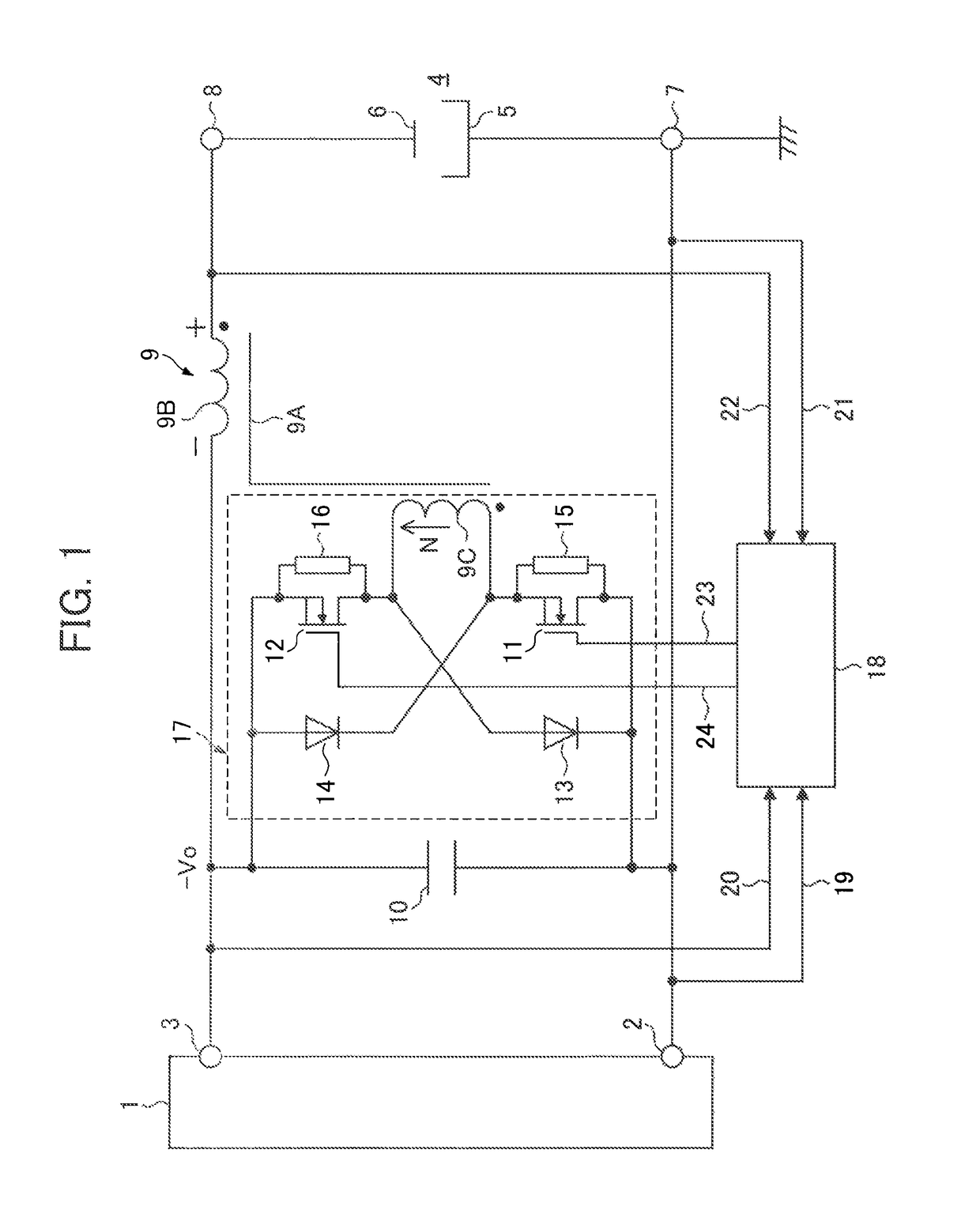
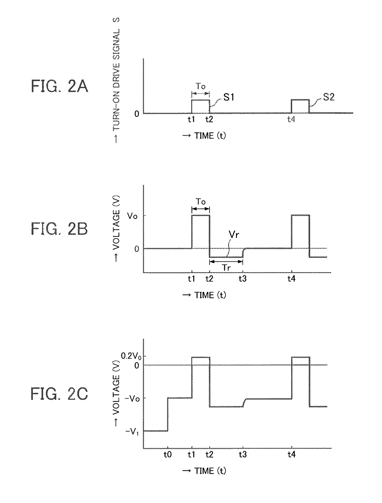
[0031]A reversed-polarity pulse generating circuit for direct current plasma according to a first embodiment of the present invention is described with reference to FIGS. 1 and 2A to 2C. FIG. 1 is a diagram showing the reversed-polarity pulse generating circuit for direct current plasma as the first embodiment according to the present invention. The reversed-polarity pulse generating circuit for direct current plasma according to the present invention causes inductance means 9 to generate, periodically or as needed, a reversed-polarity voltage pulse, whose voltage value is greater than that of direct current output voltage (hereinafter referred to as direct current voltage Vo) that is output between direct current voltage terminals 2 and 3 by a direct current power supply 1 when a plasma load 4 is in a plasma generating state, and the circuit is provided between the direct current voltage terminals 2 and 3 and load terminals 7 and 8.

[0032]The reversed-polarity pulse generating circu...

second embodiment

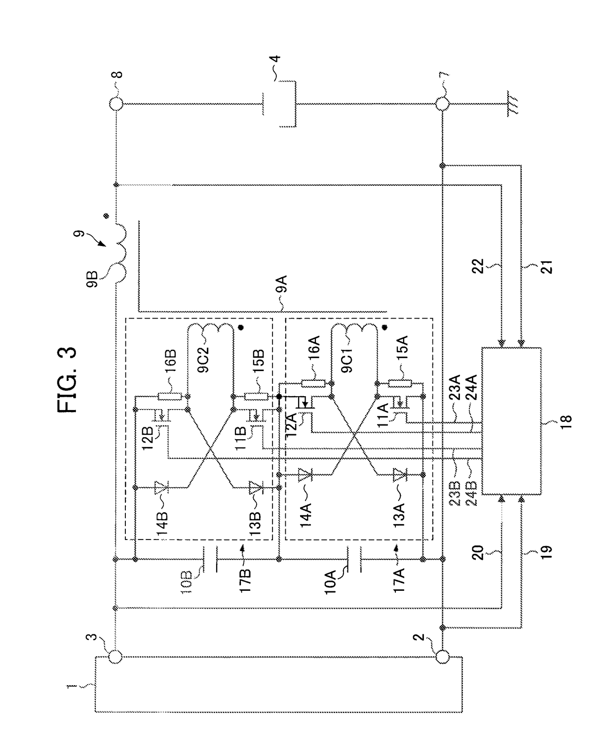
[0058]The reversed-polarity pulse generating circuit for direct current plasma according to a second embodiment of the present invention shown in FIG. 3 is mainly configured with capacitors 10A and 10B, an inductance means 9, a first unit switching circuit 17A, a second unit switching circuit 17B, and a control circuit 18. The reversed-polarity pulse generating circuit for direct current plasma according to the second embodiment of the present invention shown in FIG. 3 is characterized by including the two unit switching circuits 17A and 17B with the same circuit configuration as the unit switching circuit 17 shown in FIG. 1. More specifically, in the reversed-polarity pulse generating circuit for direct current plasma according to the second embodiment, the two capacitors 10A and 10B are serially connected with each other between a pair of direct current voltage terminals 2 and 3; the plurality of unit switching circuits 17A and 17B are connected to the two capacitors 10A and 10B, ...

third embodiment

[0070]In the reversed-polarity pulse generating circuit for direct current plasma according to the first embodiment of the present invention as described above, a first winding wire 9C of a unit switching circuit 17 is magnetically coupled with a winding wire 9B wound around a wire core 9A of an inductance means 9 through which a direct current flows, and a pulsed current is caused to flow through the second winding wire, thereby generating a reversed-polarity voltage pulse in the inductance means 9. However, since a main object of the inductance means in the direct current plasma device is to stabilize the direct current plasma electric current, a direct current naturally flows through the inductance means 9. Since the wire core 9A of the inductance means 9 is biased by way of a direct current, the size of the wire core 9A is increased. Moreover, in a case in which the plasma current is high, since the direct current flowing through the inductance means 9 is high, the winding wire ...


PUM

PropertyMeasurementUnit
voltageaaaaaaaaaa
voltageaaaaaaaaaa
breakdown voltageaaaaaaaaaa

Abstract

A capacitor is connected between direct current voltage terminals, and inductance means is connected between one end of the capacitor and one of load terminals. In a case in which the direct current voltage exceeds a set value, voltage at both ends of the capacitor is shared by the first and second switching elements that are not electrically conductive; in a case in which the direct current voltage is below the set value, the first and second switching elements are electrically conductive on a periodic basis or as needed to output reversed-polarity voltage between load terminals; and in a case in which the first and second switching elements are turned off, voltage at both ends of the capacitor restricts voltage applied to both ends of the first and second switching elements, during a period in which the first and second feedback rectifier elements are electrically conductive.

Description

[0001]The present application claims the benefit of Japanese Patent Application No. 2010-172652, filed on Jul. 30, 2010, the subject matter of which is hereby incorporated herein by reference.BACKGROUND OF THE INVENTION[0002]1. Field of the Invention[0003]The present invention relates to a reversed-polarity pulse generating circuit for direct current plasma, which generates a reversed-polarity voltage pulse being effective for suppressing or preventing occurrence of abnormal electrical discharge such as arc discharge in a direct current plasma device.[0004]2. Related Art[0005]Conventionally, in a direct current plasma device that utilizes a plasma discharge generated in vacuum, such as a sputtering device, a PVD (Physical Vapor Deposition) device, a CVD (Chemical Vapor Deposition) device, and an etching device, impedance between electrodes in the plasma load may be reduced, or foreign matter such as conductive dust may result in a short circuit between the electrodes. In such a case...

Claims


Application Information

Patent Timeline
Patent Type & Authority Patents(United States)
IPC IPC(8): H05B37/02
CPCH01J37/32027H01J37/32045H05H1/46H05H2001/4682H05H2242/22G05F1/10C23C14/54
Inventor WATANABE, KIYOMISAKAI, KAZUONAKAMURA, KENICHI
Owner ORIGIN ELECTRIC CO LTD
Why Eureka
Try Eureka