Steerable antenna
a technology of parabolic antennas and steering wheels, which is applied in the manufacture of antenna arrays, antenna details, antennas, etc., can solve the problems of noisy, high maintenance requirements, and time-consuming movement of such parabolic antennas via the motor from one satellite to another, and achieves high power amplifiers, lower cost systems, and high reliability.
- Summary
- Abstract
- Description
- Claims
- Application Information
AI Technical Summary
Benefits of technology
Problems solved by technology
Method used
Image

Examples
first embodiment
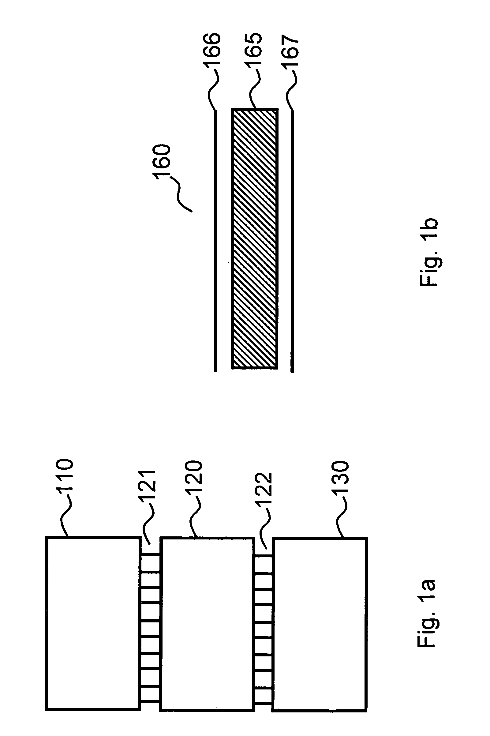
[0073]FIG. 1a is a schematic view of a multiple beam array antenna system of this invention. A beam forming network 120 with multiple inputs 121 and multiple outputs 122 is fed at least one RF signal by a means for selectively connecting 110 to at least one of the multiple inputs 121. The beam forming network 120 operates on an input RF signal applied to one of its inputs 121 to produce multiple time delayed (or phase shifted) copies with a variety of amplitudes which are modified relative to the input RF signal. An array of antenna elements 130 is connected to the multiple outputs 122. The beam forming network 120 can, in general perform steering in two dimensions, e.g. both elevation and azimuth angles. However, costs, size and weight can be minimized when the beam forming network 120 operates in a single dimension.
[0074]FIG. 1b is an exploded side view of a monolithic integration module 160. The monolithic integration module 160 comprises a dielectric layer 165 sandwiched between...
second embodiment
[0081]FIG. 3 is an exploded side view of this invention. What is shown in FIG. 3 is similar to FIG. 1b except that two more layers have been added to the construction. Those practiced in the microwave art will recognize FIG. 1b to correspond to microstrip waveguides while FIG. 3 enables stripline waveguides. Though microstrip has its advantages, e.g. two less layers and greater accessibility for adding circuit components, stripline has yet other advantages. The three main advantages of stripline construction are 1) support for true TEM propagation, 2) reduced crosstalk between nearby waveguides and 3) reduced radiation loss. The value of true TEM propagation is that fabrication tolerances are much less stringent, hence enabling lower fabrication costs. Whereas, the propagation constant for TE (transverse electric) or TM (transverse magnetic) mode propagation depends on the relationship between the wavelength (frequency) of the RF signal and the dimensions of a waveguide, the TEM mod...
third embodiment
[0086]FIG. 4 is side view of this invention, and is an example of a compacted area module. A compacted area module is herein defined a module of reduced projected area (sometimes called footprint). An example would be a compacted module with a maximal projected area of less than 90% of the surface area of its layers. Folded module 400 is a multilayer structure similar to those shown in FIG. 1b and FIG. 3, but instead of being essentially planar, folded module 400 has been formed around a single bend line. Folded module 400 is an example of a folded module. The advantage of fabricating this, and other related compacted area modules, is to reduce the overall area of a steerable phased array and hence increase its practical utility.
[0087]Ordinary circuit board fabrication techniques are incapable of creating a form as illustrated in FIG. 4 since typical microwave circuit boards are too stiff. This is due, in large part, to the fact that the starting material is typically a tri-layer wi...
PUM
 Abstract
Description
Claims
Application Information
 - R&D
- Intellectual Property
- Life Sciences
- Materials
- Tech Scout
- Unparalleled Data Quality
- Higher Quality Content
- 60% Fewer Hallucinations
Browse by: Latest US Patents, China's latest patents, Technical Efficacy Thesaurus, Application Domain, Technology Topic, Popular Technical Reports.
© 2025 PatSnap. All rights reserved.Legal|Privacy policy|Modern Slavery Act Transparency Statement|Sitemap|About US| Contact US: help@patsnap.com