
Composition for formation of upper layer film, and method for formation of photoresist pattern

a technology of photoresist film and composition, which is applied in the direction of photosensitive materials, instruments, photomechanical equipment, etc., can solve the problems of liquid droplets remaining on the photoresist film, insufficient contact angle of the layer film, water mark defect, etc., and achieve the effect of suppressing

Active Publication Date: 2014-11-25
JSR CORPORATIOON
View PDF25 Cites 1 Cited by
  • Summary
  • Abstract
  • Description
  • Claims
  • Application Information

AI Technical Summary

Benefits of technology

This patent aims to provide a composition for forming an upper layer film that can effectively suppress defects such as water mark defect and pattern defect when formed on a photoresist film during liquid immersion exposure. The composition should have sufficient transmission for exposure rays and maintain a stable film state while having a high receded contact angle. The method should also effectively suppress the generation of defects even at a high scan speed. By using this composition and method, a high-resolution photoresist pattern can be formed.

Problems solved by technology

However, the above-mentioned upper layer film has had an insufficient receded contact angle in order to achieve a high scan speed in liquid-filled exposure.
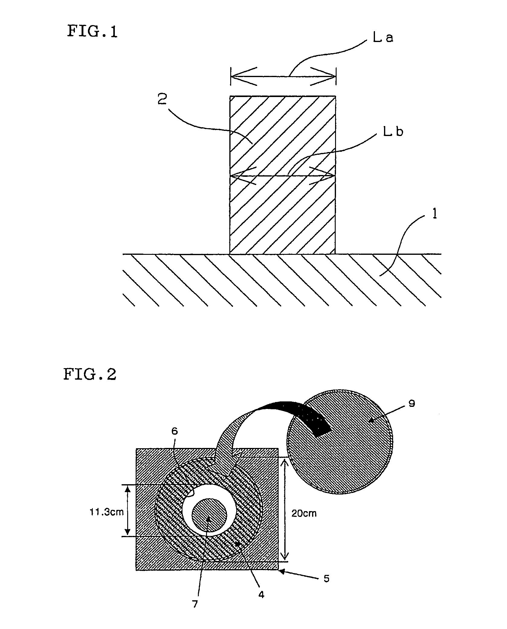
Specifically speaking, with the methods for formation of resist pattern, described in the Patent Documents 2 and 3, there can be expected the effective suppressions in water mark defect and inferior pattern defect and the formation of resist pattern of high resolution; however, there has been a fear that, with a higher scan speed, liquid droplets remain on the photoresist film owing to the insufficient receded contact angle of upper layer film and the remaining liquid droplets cause a water mark defect.

Method used


Image

  • Composition for formation of upper layer film, and method for formation of photoresist pattern
  • Composition for formation of upper layer film, and method for formation of photoresist pattern
  • Composition for formation of upper layer film, and method for formation of photoresist pattern

Examples


synthesis example 1

[0127]First, in 100 g of isopropanol were dissolved 46.95 g (85 mol %) of 1,1,1-trifluoro-2-trifluoromethyl-2-hydroxy-4-pentyl methacrylate as a monomer for production a repeating unit represented by the general formula (2-1) and 6.91 g of 2,2′-azobis-(methyl 2-methylpropionate) as an initiator, to prepare a monomer solution. Separately, 50 g of isopropanol was placed in a 500-ml three-necked flask provided with a thermometer and a dropping funnel, followed by purging with nitrogen for 30 minutes. After the purging with nitrogen, the flask inside was heated to 80° C. with stirring with a magnetic stirrer. Using the dropping funnel, the above-prepared monomer solution was dropped into the flask in 2 hours. After the completion of the dropping, a reaction was allowed to take place for 1 hour; then, 10 g of an isopropanol solution containing 3.0 g (15 mol %) of vinylsulfonic acid as a monomer for production of a repeating unit represented by the general formula (1-1) was dropped in 30 ...

synthesis example 2

[0130]First, in 50 g of methyl ethyl ketone were dissolved 50 g of 1,1,1-trifluoro-2-trifluoromethyl-2-hydroxy-4-pentyl methacrylate and 1.95 g of 2,2-azobis-(methyl 2-methylpropionate) to prepare a monomer solution. Separately, 50 g of methyl ethyl ketone was placed in a 500-ml three-necked flask provided with a thermometer and a dropping funnel, followed by purging with nitrogen for 30 minutes. After the purging with nitrogen, the flask inside was heated to 80° C. with stirring with a magnetic stirrer. Using the dropping funnel, the above-prepared monomer solution was dropped into the flask in 3 hours. After the completion of the dropping, a reaction was allowed to take place for 1 hour; then, 1.17 g of 2,2-azobis-(methyl 2-methylpropionate) was added. Thereafter, a reaction was allowed to take place for 2 hours. The flask inside was cooled to 30° C. or lower to obtain a copolymer solution.

[0131]150 g of the copolymer solution obtained was transferred to a separatory funnel. In th...

synthesis example 3

[0132]First, there were prepared separately (i) a monomer solution in which 22.26 g of 1,1,1,3,3,3-hexafluoro-2-propyl methacrylate as a monomer for production of a repeating unit represented by the general formula (1-2) and 4.64 g of 2,2-azobis-(methyl 2-methylpropionate) were dissolved in 25 g of methyl ethyl ketone, and (ii) a monomer solution in which 27.74 g of 1,1,1-trifluoro-2-trifluoromethyl-2-hydroxy-4-pentyl methacrylate as a monomer for production of a repeating unit represented by the general formula (2-1) was dissolved in 25 g of methyl ethyl ketone. Separately, 100 g of methyl ethyl ketone was placed in a 500-ml three-necked flask provided with a thermometer and a dropping funnel, followed by purging with nitrogen for 30 minutes. After the purging with nitrogen, the flask inside was heated to 80° C. with stirring with a magnetic stirrer. Using the dropping funnel, the above-prepared monomer solution (i) was dropped in 20 minutes; the mixture was subjected to aging for ...


PUM

PropertyMeasurementUnit
contact angleaaaaaaaaaa

Abstract

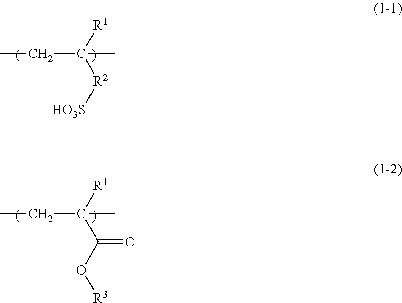
A composition for formation of upper layer film, which is used for forming an upper layer film on the surface of a photoresist film and which comprisesa resin (A) having a repeating unit represented by the following general formula (1-1) and not having a repeating unit represented by the following general formula (1-2), anda resin (B) having a repeating unit represented by the following general formula (1-2) and not having a repeating unit represented by the following general formula (1-1).[In the general formulas (1-1) and (1-2), R1 is hydrogen or the like; R2 is single bonds or the like; and R3 is a fluorine-substituted, linear or branched alkyl group having 1 to 12 carbon atoms, or the like.] The composition can form an upper layer film giving a sufficiently high receded contact angle.

Description

TECHNICAL FIELD[0001]The present invention relates to a composition for formation of upper layer film, which is useful for forming an upper layer film capable of, in liquid immersion exposure conducted for finer lithography, protecting a photoresist film and suppressing the dissolution of photoresist film components to protect the lens of projection aligner, as well as to a method for formation of photoresist pattern using the composition for formation of upper layer film.BACKGROUND ART[0002]In producing a semiconductor element, etc., there is used a projection aligner of stepper type or step and scan type, which can transfer a reticle (a photomask) pattern onto the to-be-irradiated areas of a wafer having thereon a photoresist film (hereinafter referred to as “photoresist” in some cases) formed by coating, via a projection optical system. The projection optical system of projection aligner gives a higher resolution as the wavelength of the exposure ray used is shorter and the numer...

Claims


Application Information

Patent Timeline
Patent Type & Authority Patents(United States)
IPC IPC(8): G03F7/20G03F7/38G03F7/11G03F7/30
CPCG03F7/2041G03F7/11G03F7/004G03F7/0045G03F7/0046G03F7/0047
Inventor NISHIMURA, YUKIOSUGIE, NORIHIKONAKASHIMA, HIROMITSUNATSUME, NORIHIROKOUNO, DAITA
Owner JSR CORPORATIOON
Learn More