Ion/proton-conducting apparatus and method

a proton-conducting membrane and apparatus technology, applied in the direction of phosphorus oxyacids, crystal growth process, electrochemical generators, etc., can solve the problems of device failure, use of pulsed laser deposition to create ceramic thin film, and high cost of platinum catalysts for oxidation and reduction reactions in fuel cells. , to achieve the effect of improving performance, easy and inexpensive coating, and reducing temperatur

Inactive Publication Date: 2014-12-23
UNIVERSITY OF ROCHESTER
View PDF0 Cites 3 Cited by
  • Summary
  • Abstract
  • Description
  • Claims
  • Application Information

AI Technical Summary

Benefits of technology

[0018]An embodiment of the invention is directed to a method for making an ion- / proton conducting membrane. The method includes the steps of creating a seeded surface by depositing a sufficiently dense HAP seed layer on a hydrogen membrane cathode electrode, hydrothermally synthesizing a c-axis-oriented, crystalline HAP film on the seeded surface in a secondary, single crystallization substantially normal to the seeded surface, and hydrothermally densifying the HAP film in an a-axis orientation perpendicular to the c-axis orientation in a tertiary crystallization to form a gas-tight thin film. In a non-limiting aspect, the seed layer is electrochemically directly grown on a pure palladium hydrogen membrane cathode electrode. By optimizing proton transport, fuel cells may have improved performance and be operated at lower temperatures than possible with standard ceramic membranes. In addition, by growing the proton conducting membrane electrochemically directly onto hydrogen membranes, the proton conductor can easily and inexpensively be coated onto large surface areas and onto tubular geometry often used for hydrogen membranes. According to an aspect of the method, palladium embrittlement can be mitigated by reducing an amount of evolved hydrogen at the cathode electrode. This may be accomplished by applying an electrical current equal to or less than 10 mA / cm2 and / or limiting the deposition time to between about five minutes to one minute. According to an aspect, the method involves controlling supersaturation of HAP to mediate crystal nucleation and growth to achieve thin film densification and / or to control the resulting thickness of the thin film; advantageously, controllably reducing the film thickness from about 10 μm to 1-2 μm or less.

Problems solved by technology

The ion exchange membranes in PEMFCs are polymers that function most effectively below 100° C. There are no polymeric ion conducting membranes reported that operate effectively above 200° C. The upper temperature limit on polymeric ion conducting membranes means that expensive platinum catalysts should be used for the oxidation and reduction reactions in fuel cells.
However, the SOFC operating temperature is sufficiently high that stress from thermal cycles can, and often does, lead to device failure.
One significant limitation in the HMFC described above is the use of pulsed laser deposition to create the thin film of ceramic on palladium.
Pulsed laser deposition is a high vacuum technique that is known to be unsuitable for economically coating large surface areas (the reported HMFC was in the shape of a circle only six millimeters in diameter).
The pulsed laser deposition technique is also difficult to employ to coat non-planar substrates.
However, there is no reported study to date of high temperature proton conductivity in singe crystals of HAP due to the difficulty to synthesize large-sized HAP single crystals.
Electrochemical growth onto palladium membranes is particularly challenging due to hydrogen embrittlement.
Embrittlement refers to the membrane warping and damage that occurs when pure palladium is exposed to hydrogen at temperatures below 293° C. The use of palladium alloys rather than pure palladium mitigates warping to some extent, but does not eliminate issues of hydrogen embrittlement.

Method used


Image

  • Ion/proton-conducting apparatus and method
  • Ion/proton-conducting apparatus and method
  • Ion/proton-conducting apparatus and method

Examples


Embodiment Construction

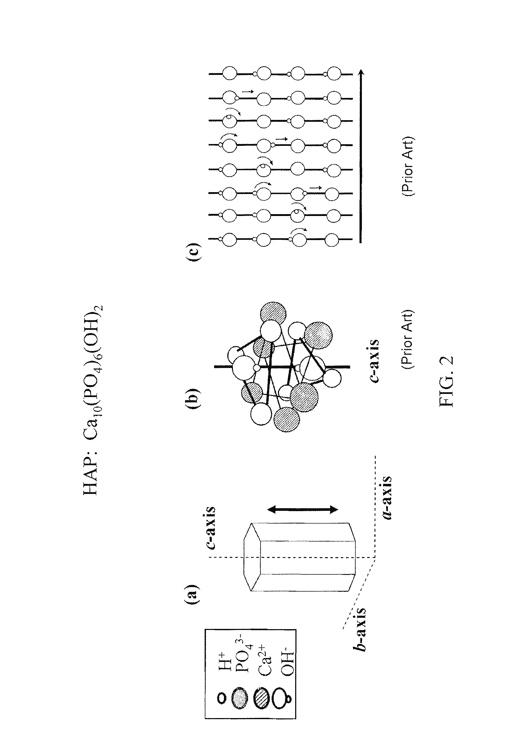
[0064]As mentioned above, optimal performance of a hydroxyapatite ion- / proton-conducting membrane occurs when the crystal domains span the entire thickness of the membrane to eliminate grain boundary resistance across the thickness of the crystal. In addition, the crystal's c-axis would be aligned so that the proton transport path is optimized, as illustrated in FIGS. 2(a-c).

[0065]FIG. 3(a) schematically shows HAP crystals that are randomly oriented. FIG. 3(b), on the other hand, schematically shows an ideal HAP membrane structure with the c-axes of crystal domains spanning the entire membrane thickness to optimize proton transport;

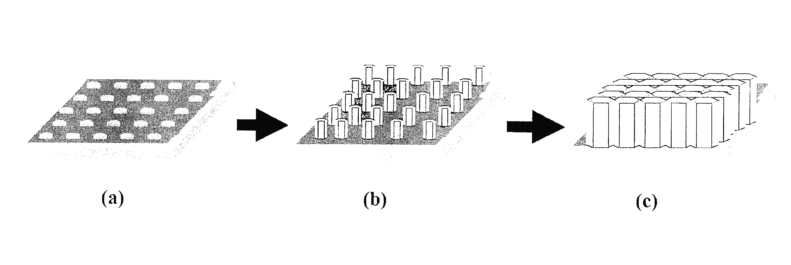
[0066]A non-limiting, exemplary ion / proton conducting membrane 400-1 as illustrated in FIG. 4(c) includes a substrate 402 and a crystalline ion-conducting thin film 304 (also shown in FIG. 3(b)) having a thickness t. The thin film is characterized by a plurality of single apatite crystals 304′ each having its c-axis oriented normal to the substrate (as al...


PUM


Abstract

A c-axis-oriented HAP thin film synthesized by seeded growth on a palladium hydrogen membrane substrate. An exemplary synthetic process includes electrochemical seeding on the substrate, and secondary and tertiary hydrothermal treatments under conditions that favor growth along c-axes and a-axes in sequence. By adjusting corresponding synthetic conditions, an HAP this film can be grown to a controllable thickness with a dense coverage on the underlying substrate. The thin films have relatively high proton conductivity under hydrogen atmosphere and high temperature conditions. The c-axis oriented films may be integrated into fuel cells for application in the intermediate temperature range of 200-600° C. The electrochemical-hydrothermal deposition technique may be applied to create other oriented crystal materials having optimized properties, useful for separations and catalysis as well as electronic and electrochemical applications, electrochemical membrane reactors, and in chemical sensors. Additional high-density and gas-tight HAP film compositions may be deposited using a two-step deposition method that includes an electrochemical deposition method followed by a hydrothermal deposition method. The two-step method uses a single hydrothermal deposition solution composition. The method may be used to deposit HAP films including but not limited to at least doped HAP films, and more particularly including carbonated HAP films. In addition, the high-density and gas-tight HAP films may be used in proton exchange membrane fuel cells.

Description

RELATED APPLICATION DATA[0001]The instant application is a continuation-in-part (CIP) of U.S. non-Provisional application Ser. No. 13 / 083,737, filed on 11 Apr. 2011, which in turn is a divisional application of U.S. non-provisional application Ser. No. 12 / 392,150, filed on 25 Feb. 2009, now U.S. Pat. No. 7,943,269, which in turn claims priority to U.S. Provisional application Ser. No. 61 / 031,492 filed on Feb. 26, 2008 and to U.S. Provisional application Ser. No. 61 / 101,314 filed on Sep. 30, 2008, the subject matters of which are hereby incorporated by reference in their entireties.FEDERALLY SPONSORED RESEARCH[0002]This invention was made with government support under Contract Nos. DE-FG02-05ER15722 and DE-FC03-92SF19460 awarded by the United States Department of Energy, and under Contract No. CMMI-0856128 awarded by the National Science Foundation (NSF). The government has certain rights in the invention.BACKGROUND[0003]1. Field of the Invention[0004]Embodiments of the invention per...

Claims


Application Information

Patent Timeline
Patent Type & Authority Patents(United States)
IPC IPC(8): B05D5/12H01M8/10H01M8/12C30B29/14
CPCY02E60/525Y02E60/521H01M8/1016C30B29/14H01M2008/1293H01M8/1004H01M2300/0068Y02E60/50
Inventor YATES, MATTHEWXUE, WEI
Owner UNIVERSITY OF ROCHESTER
Why Eureka
Try Eureka