

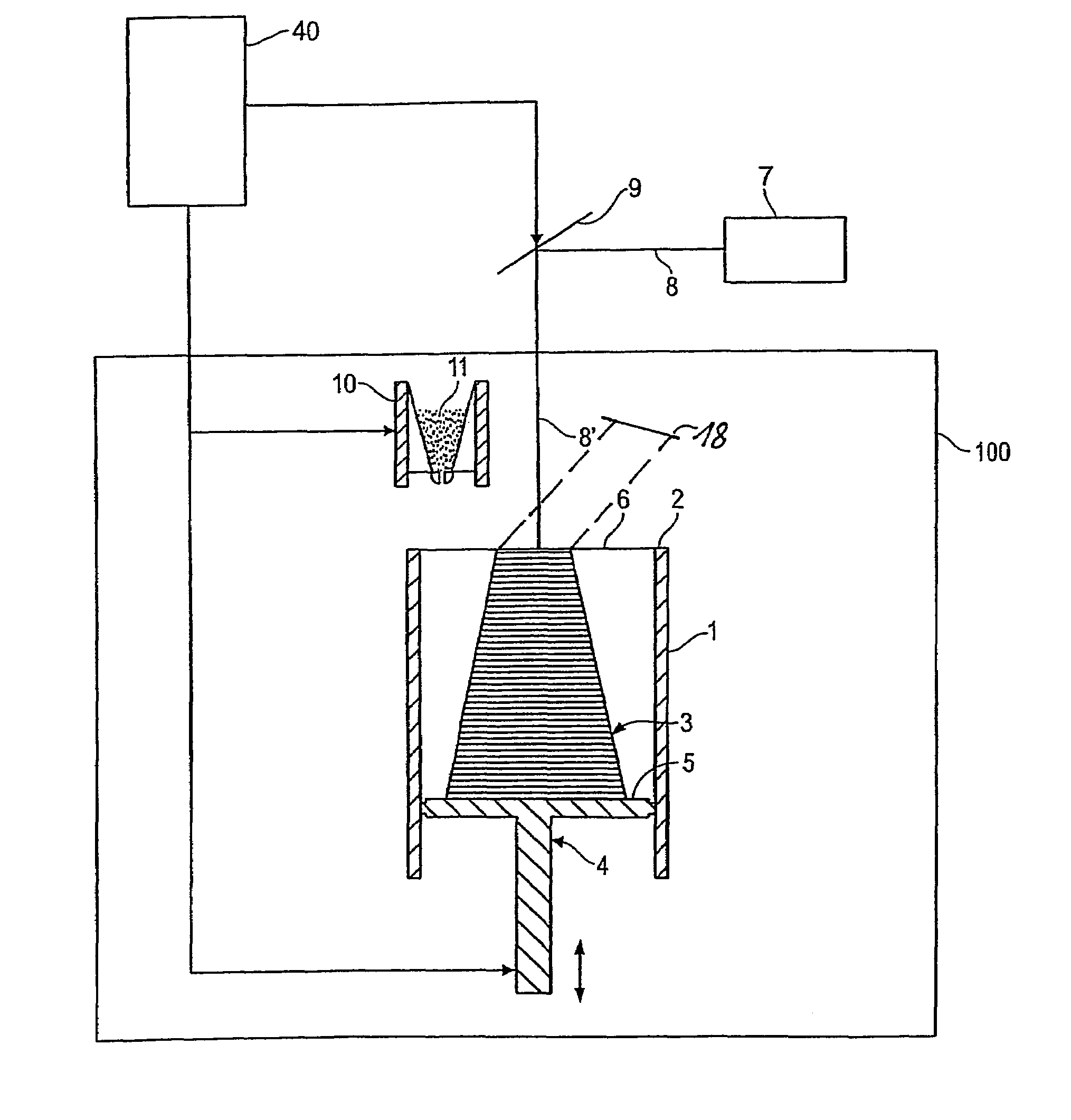
Method for a layer-wise manufacturing of a three-dimensional object
a three-dimensional object and manufacturing method technology, applied in additive manufacturing processes, additive manufacturing with solids, coatings, etc., can solve the problems of slow exposure process, expensive acquisition and service of lasers, slow exposure time, etc., to reduce the requirement for cooling, reduce beam energy, and reduce the effect of irradiation tim
- Summary
- Abstract
- Description
- Claims
- Application Information
AI Technical Summary
Benefits of technology
Problems solved by technology
Method used
Image

Examples
first embodiment
[0061]The first embodiment of the invention makes use of the fact that the powder material can change color due to the action of the electromagnetic radiation or particle radiation. As this was first observed for thermoplastic polymers, in the first embodiment as an example polyamide 66 powder is used as building material, wherein the polyamide 66 powder has not been thermally stabilized. However, also all other thermoplastics and thermo-elastics such as polyethylene (PE, HDPE, LDPE), polypropylene (PP), polyamides, polyester, polyester ester, polyether ester, polyphenylene ether, polyacetals, polyalkylene terephthalates, in particular polyethylene therephthalate (PET) and polybutylene terephthalate (PBT), polymethyl-methacrylate (PMMA), polyvinylacetal, polyvinylchloride (PVC), polyphenylene oxide (PPO), polyoxymethylene (POM), polystyrene (PS), acrylonitril-butadiene-styrene (ABS), polycarbonates (PC), polyether sulphones, thermoplastic polyurethanes (TPU), polyaryletherketones, i...
second embodiment
[0067]In order to increase the change of the absorption when electromagnetic radiation or particle radiation is applied, the base material that is used may be mixed with additives. These additives can change their absorption to such an extent that also a noticeable change of the absorption of the mixture can be observed. Furthermore, by the systematic adding of additives a sensitivity for a certain radiation (for example a radiation having a certain wavelength) can be brought about systematically. Here, the sensitivity can be increased for a directed beam for a selective exposure (for example for laser light having a certain wavelength). A systematic increase of the sensitivity for the radiant heater is also conceivable. As additives are possible[0068]all established colorants (dyes and pigments) that absorb in the UV-VIS and / or the infrared region[0069]additives that have their absorption maximum particularly in the near infrared region: such as Lumogen IR765 and Lumogen IR788 of B...
third embodiment
[0080]In the third embodiment polyaryletherketone powder is used as building material. Polyaryletherketones as building material are particularly interesting, because parts manufactured from PAEK-powder feature a good bio-compatibility as well as a high resistance against hydrolysis and radiation. In particular, the thermal resistance also at elevated temperatures as well as the chemical resistance characterize PAEK-powders with respect to conventional plastic powders. Due to these properties PAEK materials are in demand particularly in the automotive and electronics industry as well as the medical industry. In particular, such a PAEK-polymer powder may be a powder from the group polyetheretherketone (PEEK), polyetherketoneketone (PEKK), polyetherketone (PEK), polyetheretherketoneketone (PEEKK) or polyetherketoneetherketoneketone (PEKEKK).
[0081]However, with respect to the powder sintering or melting PAEK-powders involve the disadvantage that the melting point of the material lies a...
PUM
| Property | Measurement | Unit |
|---|---|---|
| wavelength | aaaaa | aaaaa |
| wavelength | aaaaa | aaaaa |
| wavelength region | aaaaa | aaaaa |
Abstract
Description
Claims
Application Information