These can present an overwhelming and difficult to understand picture of the state of the art of pitch production.
In addition to the published art on pitch making, there is much unpublished lore on the difficulties of making pitch without coking up the heaters and shutting the process down, though some of this difficulty can be inferred by the extreme steps taken to stop thermal
polymerization just short of coking.
The
asphalt forms a sticky mess that is difficult to remove.
Part of the reason for the proliferation of processes is that many approaches work well in the lab but not in practice.
Pitch processes can be difficult to run, as evidenced by few commercial processes still in operation.
Coking conditions are so severe that
long chain molecules are cracked into olefinic molecules that in turn are cracked to form reactive dienes.
Coker
naphtha is one of the main byproducts, but is unstable and difficult to process primarily because of the
diene content.
If coker
naphtha is used in a car as
gasoline, it forms gum and rapidly clogs filters, injectors and the like.
There are some flaws in this approach.
Large complex refineries have the specialized equipment needed to process coker
naphtha.
Although it is possible to calculate with great accuracy an ERT, in practice it is hard to determine what ERT was used in a particular process.
Many experiments reported in the
patent literature may not include enough detail about, e.g., liquid
residence time to permit an accurate calculation.
In addition, not much is known about the flow regimes in tubes for exceedingly heavy liquid products.
Although pitch manufacturing has been practiced for millennia, the process is not easy.
Athabasca
tar sands are too heavy to process in a conventional
refinery.
Many heavy crudes are both too viscous and contain too much
metal and other impurities to permit refining in a conventional
refinery.
For such difficult feeds refiners have installed cokers that heat the difficult feed to a temperature sufficient to induce thermal reactions and let the heated feed sit in a
coke drum for hours or days.
These can be processed with some difficulty in a conventional
refinery.
Heat the feed enough to induce thermal
polymerization and give it enough time, it will inevitably form
coke.
In contrast, thermal
processing is difficult when the end product is something short of
coke.
When isotropic pitch is the desired product, more problems can exist, even if conditions are selected to minimize coke formation.
Coke is an obvious problem on the road to pitch while mesophase—the penultimate stop on the road to pitch—is hard to see and even harder to avoid.
Mesophase pitch and isotropic pitch are often produced simultaneously and unintentionally.
The presence of modest amounts of mesophase in an isotropic pitch product destroys most of the value of the isotropic pitch.
In all processes using thermal polymerization, it is hard to achieve this polymerization without coking up the heater tubes used to reach these extreme temperatures.
Hot
metal surfaces promote coke formation on the walls of the tubes in the heaters and cause rapid
fouling.
These processes produce pitches suitable for low value uses such as those in which nearly any pitch is satisfactory; however, for high end uses especially as precursors for carbon
fiber manufacture, pitches produced from air blowing are not satisfactory.
However, the carbon particles in the pitch are detrimental to use of the pitch as an impregnating agent or as a precursor for producing
carbon fibers.
Multiple step
processing of the feed, and the need to recycle so much of the first stage
effluent added significantly to the cost of capital and operations.
Furthermore, the bottoms product from this first stage was not the desired product.
Such an approach and many more reported in the
patent literature would make isotropic pitch, but the approach was complex and the yields were low.
A
disadvantage of all of the processes described above is that the yields per pass of pitch from the feedstocks are low.
This increases the volume and cost of heating the reactor charge.
Fractionation is costly when relatively large amounts of light materials such as naphtha boiling range or light distillate materials must be removed from heavy distillate materials being recycled to the pitch heater.
When pitch manufacturers have to separate a relatively small amount of naphtha from a large amount of recycle gas oil fraction and then have to recycle a large amount of gas oil to convert some of it to pitch, capital and operating costs multiply.
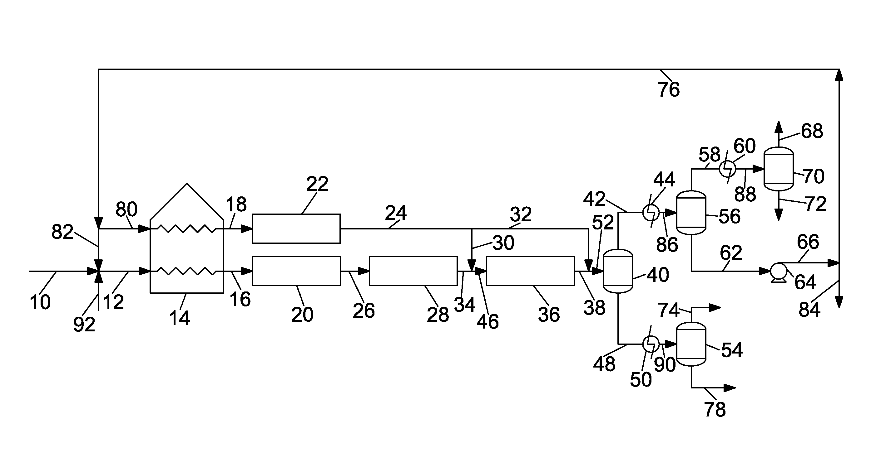
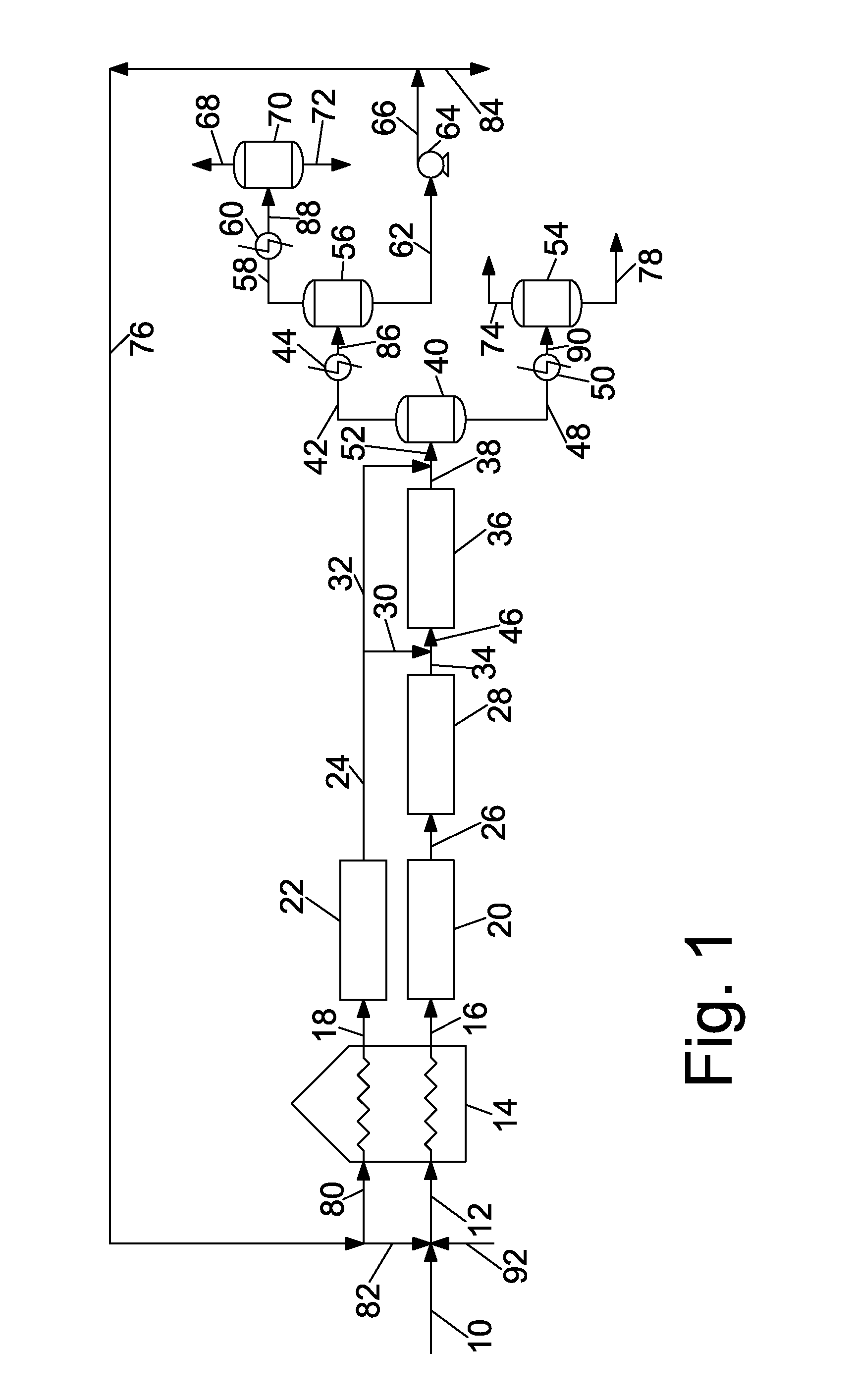
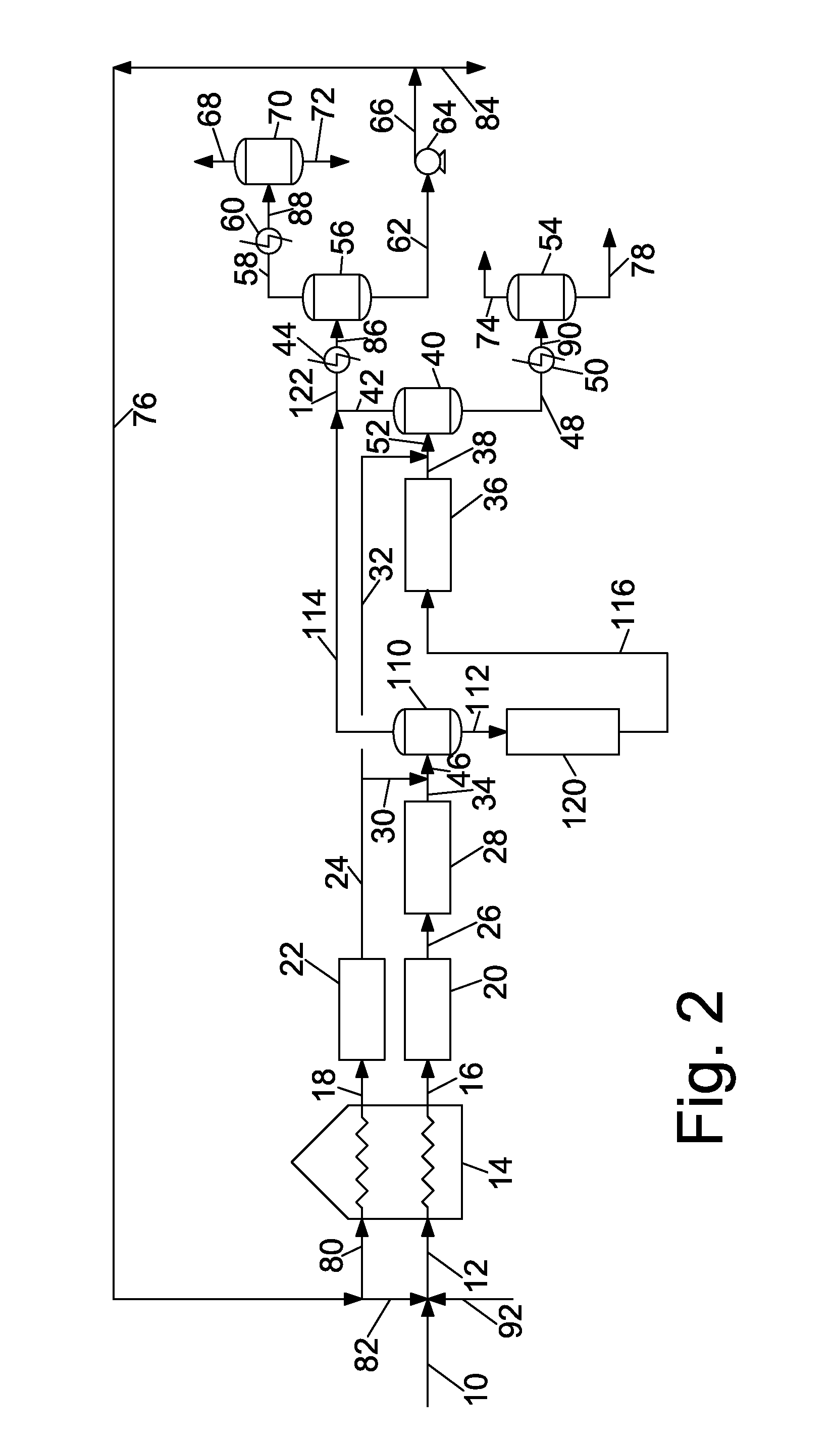
Many refiners would like to be able to recover pitch product downstream of the thermal reactors using a simple flash drum, and recover a recycle gas oil fraction by simply condensing vapors from the flash drum, but no one has been able to do so.
Another fundamental challenge in producing highly aromatic pitch is operating at temperatures and
residence times to maximize the yield of isotropic pitch without producing significant coke or mesophase.
If the time and temperature are low, conversion rates are low, resulting in low yields.
If the time and temperature are too high, coke can form, clogging equipment and / or producing pitch contaminated with coke particles.
If conditions are severe, some mesophase can form and this is a contaminant when isotropic pitch is the desired product.
Especially troubling was the low “productivity” of current continuous pitch processes, with low conversions of reactor feed per pass through the reactor, typically on the order of 10-15%, and always less than 20%.
All known prior art continuous processes used relatively mild conditions, i.e., they operated with conditions so mild that conversion of the feed was limited.
In addition to concerns about coking or making isotropic pitch with contaminating mesophase, there are more constraints on the isotropic pitch product.
Such an approach works, but wiped film evaporators are expensive to buy and operate and have relatively low capacity.
We obtained promising results, but had plugging problems.
We achieved significant conversion per pass but there was still some coke formation and product purity was not as high as desired in that there was usually some mesophase pitch present in and contaminating the isotropic pitch product.
We were able to get relatively high conversion, higher than anything reported or known in the prior art but had trouble getting an acceptable run length, due to coking or
fouling of the tubular reactor, at times exacerbated by equipment failures.
This run with steam produced an awful product.
This was an intolerable amount of mesophase for an isotropic pitch product.
We had thought steam would help by increasing velocity or perhaps being a reactant, but found that steam hurt the process in some way, perhaps by creating a pseudo vacuum reducing the effective pressure and reducing the amount of the feed that was in
liquid phase.
Although we had significant conversion of feed to pitch, there was relatively low yield of gasoline boiling range material, and the gasoline appeared to be highly aliphatic—lower in olefin content than any gasoline fraction produced by any prior thermal process whether mild visbreaking or severe coking.
Our gasoline production was small.
There was enough gasoline boiling range material in our process and in all prior art processes that it would be harmful to the process to simply recycle a gas oil
stream containing large amounts of readily vaporizable material such as gasoline.
Our process required high temperatures and sufficient
residence time to make pitch, but did not make unstable gasoline.
In contrast, prior art pitch processes limited conversion, per pass to such an extent that the reactor
effluent was too dilute to “flash”.
High conversion per pass was a necessary part of our process, but from our failed experiments with
steam injection we learned that
high pressure, high temperature and high tube velocities were not enough to ensure that a salable pitch product could be made.

