Method for inhibiting corrosion

a corrosion inhibitor and corrosion technology, applied in the direction of chemical reaction analysis, material testing goods, instruments, etc., can solve the problems of acidic water produced in the extraction of oil, initiation or acceleration of corrosion in these systems, and acidic compounds can be extremely corrosive, so as to reduce the limit of detection and/or the accuracy and precision of monitoring methods, reduce surface tension, and reduce interfacial tension

Active Publication Date: 2016-06-07
ANPERA TECH LTD
View PDF15 Cites 8 Cited by
  • Summary
  • Abstract
  • Description
  • Claims
  • Application Information

AI Technical Summary

Benefits of technology

[0024]Preferably, a compound capable of associating with a micelle to produce an amplified signal may be added to the fluid to be analysed, thereby improving the limit of detection and / or the accuracy and precision of monitoring methods.
[0025]In the context of the invention, the term “amphiphilic” refers to the property of a molecule having a water-soluble polar head (hydrophilic) and a water-insoluble organic tail (hydrophobic). A “surfactant” is a compound that is surface active and reduces surface tension when dissolved in a liquid, or that reduces interfacial tension between two liquids or between a liquid and a solid.

Problems solved by technology

Water produced in the extraction of oil is typically acidic, especially in the presence of carbon dioxide and / or hydrogen sulphide which are often present during the extraction process.
Bacteria found in industrial environments, particularly sulphate-reducing bacteria, can initiate or accelerate the corrosion in these systems.
These acidic compounds can be extremely corrosive and corrosion inhibitors may be added to the fluids that come into contact with metallic surfaces.
Corrosion is a growing problem particularly for older oil wells, since the composition of produced fluids changes from predominantly hydrocarbons to hydrocarbon / brine mixtures to predominantly brine with lower hydrocarbon yields.
Gas wells also suffer from increasing corrosion with age due to the increased exposure to corrosive environments.
The inhibitor may also be lost with the produced fluids for example when it is injected down a well and is then brought up within the oil and water.
Corrosion inhibitor formulations are complex chemical mixtures and difficult to monitor because of the large number of components involved.
Few monitoring methods measure all components of a formulation.
However, this approach is limited to the monitoring of specific classes of chemicals.
A disadvantage of the ion pair technique is that the method is restricted to formulations with known chemical composition and needs to be tailored to the components of the composition.
Another disadvantage is that the limit of detection of the ion pair technique is generally only about 5 ppm for inhibitor residuals.
These methods are prone to error from other absorbent or fluorescent species.
However, this method is time-consuming, uses expensive and bulky equipment that is not suitable for offshore manipulation, and requires regular maintenance.
ESI MS-MS systems must be handled by skilled technicians and do not normally provide quantitative information.
Less sophisticated mass spectrometry variations can be used but they are less informative and are still complicated and laboratory based.
However, chemical companies rarely release information on the exact components of their corrosion inhibitor formulation and service companies often bind operators to “non-analysis agreements” to specifically stop them from analysing their formulations for chemical composition.
Interpretation of results can therefore be difficult.
However, these methods are specific to a particular location rather than the full conduit.
The information from the coupon is an additive effect of typically three months and so the temporal resolution of this monitoring system is very low.
Further, although information on the corrosive capacity of a system is available, no direct information on levels of corrosion inhibitor residuals is provided.
Many of the techniques described above can only be used in aqueous systems and are unsuitable for fluids comprising larger amounts of oil.
False increase or decrease in signal from interferences means levels have significant uncertainty.
All the techniques are susceptible to interferences and oil components often need to be extracted from the water sample to be analysed.
The extraction process can be time consuming and technically difficult.
In addition, inhibitor may be lost during the extraction process.

Method used


Image

  • Method for inhibiting corrosion
  • Method for inhibiting corrosion
  • Method for inhibiting corrosion

Examples


experiment a

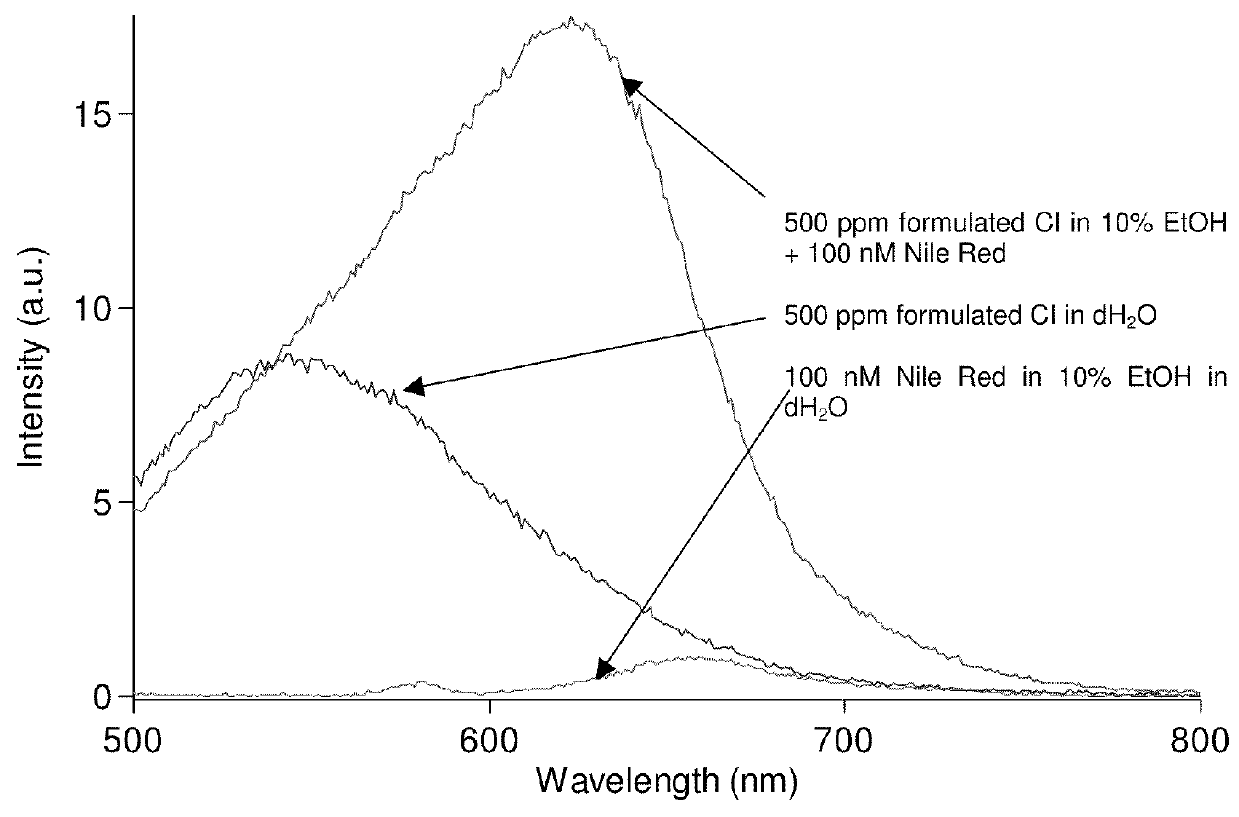
[0070]Use of fluorescence spectroscopy to demonstrate the differences observed in corrosion inhibitor micelles relative to an aqueous solution and the further differentiation that can be obtained by adding a marker molecule to a sample.

[0071]The instrument used was a Varian Carey Eclipse spectrofluorometer with a standard 1 cm fluorescence cuvette. Excitation was at 485 nm with 5 nm slit widths for excitation and emission. A stock solution of marker (1 μM Nile Red, Sigma) was prepared in spectroscopic grade ethanol (Fisher) and diluted ten-fold with deionised water. The fluorescence emission spectrum was weak with a maximum intensity at 655 nm.

[0072]Addition of a commercially available oilfield corrosion inhibitor (product name “EC1440A”, known to have an active imidazoline-based component and to include alcohols) at a level of 500 ppm total to deionised water created a micellular dispersion with some fluorescence intensity maximised at 545 nm. To this solution, addition of Nile Red...

experiment b

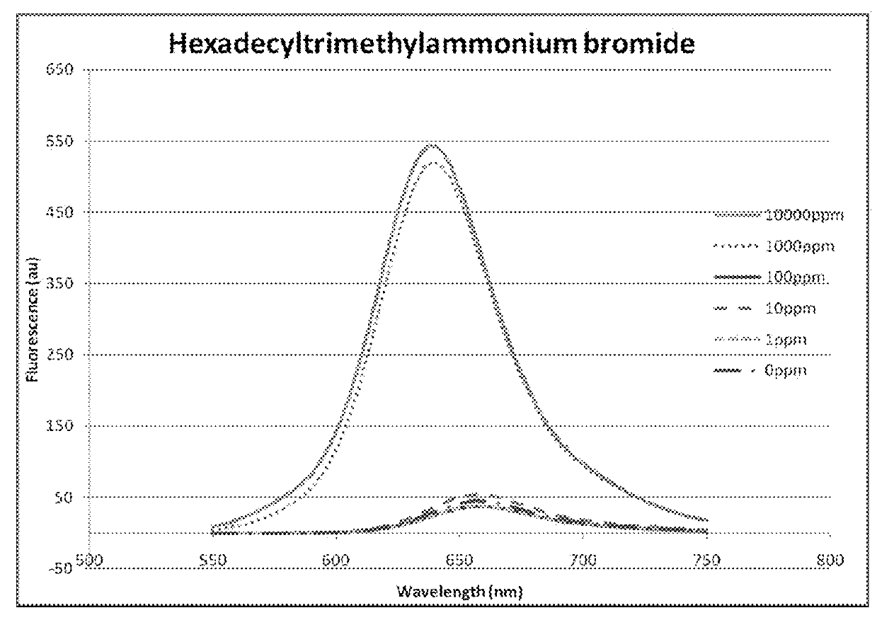
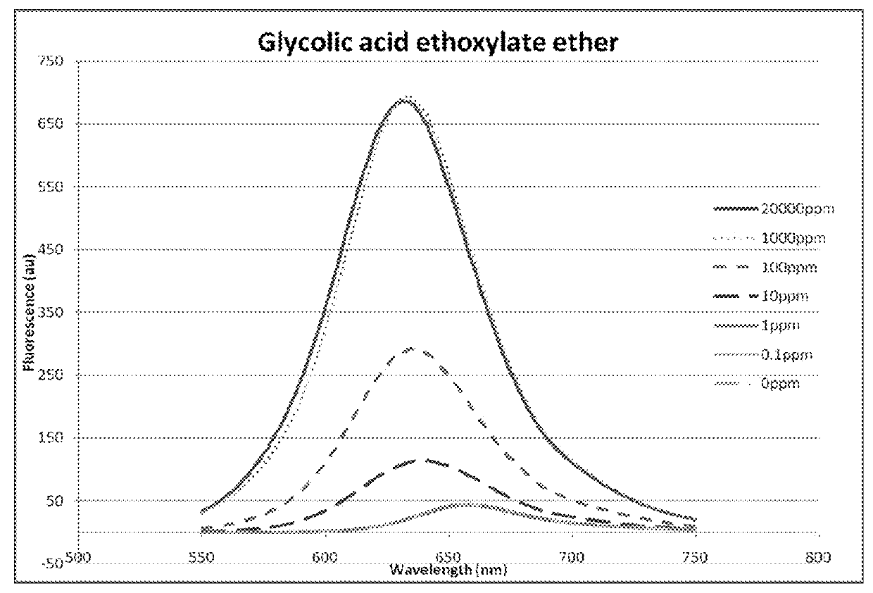
[0075]Use of fluorescence spectroscopy to demonstrate the differences observed in corrosion inhibitor micelles using different concentrations of different amphiphilic chemicals.

[0076]Three amphiphilic chemicals belonging to different chemical classes were used to determine the fluorescent response of a marker molecule over a range of concentrations. The three chemicals were hexadecyltrimethyl-ammonium bromide (commonly known as cetrimonium bromide), glycolic acid ethoxylate oleyl ether and cetylpyridium bromide hydrate. Concentrated solutions of each were prepared in water (1%, 2% and 1%, respectively) and serial dilutions of each were performed in to water so that 1000, 100, 10, 1 and 0.1 ppm samples were also available. Each sample was analysed using the same method.

[0077]The same equipment as that used in Experiment A was used to collect fluorescence emission spectra, however, an excitation wavelength of 530 nm was used. To each test sample, 3 μL of 1 mM Nile Red (Sigma) in spect...

experiment c

[0080]Use of fluorescence spectroscopy and other physical measurements to detect corrosion inhibitor micelles in multi-phase field fluids.

[0081]The corrosion inhibitor used was a proprietary composition, known to be film-forming, i.e. surfactant in nature. The corrosion inhibitor (“RU-276”) was known to have more than one active component, one of which was known to be imidazoline-based. The multi-phase fluid comprised a synthetic field brine and complementary oil from the same field. The oil was a black oil with API ˜21° and was present at 10% of the total fluid volume to simulate a production facility with high water cut where corrosion control is important.

[0082]Samples of this multiphase fluid with different corrosion inhibitor concentrations were prepared by adding various amount of the inhibitor to the aqueous phase of the fluids. The samples were mixed on a horizontal rotary shaker for 20 minutes and allowed to settle for a minimum of four hours. Some of the samples formed an ...


PUM

PropertyMeasurementUnit
sizeaaaaaaaaaa
wavelengthsaaaaaaaaaa
excitation wavelengthaaaaaaaaaa

Abstract

A method for inhibiting corrosion comprises the steps of providing a fluid; adding a corrosion inhibitor comprising at least one amphiphilic chemical to the fluid; and monitoring micelles presence in the fluid. A method for determining the amount of corrosion inhibitor that is sufficient to inhibit corrosion, a method for monitoring the activity of an amphiphilic chemical and a system for inhibiting corrosion in a conduit are also disclosed.

Description

CROSS-REFERENCE TO RELATED APPLICATIONS[0001]This application is the U.S. National Stage of International Application No. PCT / GB2009 / 001803, filed Jul. 20, 2009, which claims priority to British Application No. 0813278.9, filed Jul. 18, 2008.FIELD OF THE INVENTION[0002]The application relates to a method for inhibiting corrosion and to a method for monitoring the effective concentration of corrosion inhibitor in a fluid. The invention is based on the use of micelle formation as an indicator of effective corrosion inhibitor concentration.BACKGROUND OF THE INVENTION[0003]In the oil and gas industry and in the petrochemical industry, fluids are commonly transported and processed in metal pipes and conduits, typically made of steel. These pipes and conduits carry fluids containing amounts of oil and / or water and are also likely to contain hydrocarbon or other gases and solids. The solids can arise from the rock formation or due to the presence of in situ chemical deposits (e.g. scale, w...

Claims


Application Information

Patent Timeline
Patent Type & Authority Patents(United States)
IPC IPC(8): C23F11/08C23F11/00C09K8/54C23F11/10
CPCC23F11/00C09K8/54C23F11/10
Inventor MACKENZIE, CAMERONMAGDALENIC, VJERAMOUSSAVI, ARTINJOOSTEN, MICHAELACHOUR, MOHSENBLUMER, DAVID J.
Owner ANPERA TECH LTD
Why Eureka
Try Eureka